When we are pushing the limits, we are going to encounter fails. But through failure comes knowledge and at times, it even brings about extra creativity. On that note, I hope 2017 brings you many fails!
In December, I did a last minute contribution to the A Pyro Design Maker Coin Holiday Tree. In my coin, I wanted to celebrate the failures that comes along with learning 3D Printing. I call it, “From Failure Comes Knowledge“. This video details the inspirations behind the coin, a little taste of the modeling in Blender, and the [embarrassing] two fails I had printing it.
Last Thursday night, I had the delight of participating in a Meetup with the Delaware 3D Printing Group. The event was hosted by Printed Solid. The group was kind enough to let me yammer on about my 3D Printed Crafts. 🙂 I very much enjoyed chatting with other printing enthusiasts and left the event invigorated. I should make it a point to do an event like this every November when the fatigue that accompanies Cyber Week looms in my brain. 🙂
My very first Thingiverse upload was glowing pumpkin pendants/pins for kids. This video hits briefly on how I print these via Multi-processes in Simplify3D (Spoiler alert – they are three separate prints). It will also show you how you can import in the pendant template into TinkerCAD and quickly make your own customizations. Finally, have a drawing you want to use? I’ll go over using Inkscape to make a SVG file from a black and white image/photo/scan that you can also pull into TinkerCAD to “carve” your pumpkin.
As some background information, the way the MakerGear M2 Homes its Z axis is it has a bolt on the platform that raises and lowers your bed.
Above it, just beneath the X-axis rail, is a switch that triggers when there is contact.
When the printer is homing its Z axis, it raises the bed until the bolt triggers that switch. At that point, the printer considers itself a Z-Home.
MakerGear has some great videos for the maintenance and setup of your machine, including how to do your Z Endstop calibration! Basically you raise your bed until a business card can just fit under the nozzle and then you raise the bolt to ensure it trips the switch at that exact height.
Disclaimer– I love my MakerGear M2 profusely and I will continue to love it profusely. That said, I find the bolt awkward and tough to raise.
One day I needed to update my Z Endstop application and I struggled getting that bolt to do my bidding.
“If only…if only I had something to stick on top of this bolt to make it taller.” I thought.
It turns out I did have something, something that was already a part of my 3D Printing arsensal– Painter’s Tape!
I cut out little squares of painters tape, made a tower, put it on top of my bolt. I fine tuned the tower’s height until my nozzle was a business card height above my bed. BAM! ZEndstop calibration!
Honestly, I never expected this solution to have the staying power it has, but I continue to use it to this day! I was worried about the repeatability of the Z-Home, that there would be variances in run to run in how the painter’s tape compresses, but it has proven to be consistent and reliable. I have also been shocked (SHOCKED) that it weathers travel well.
I have found this painter’s tape hack to help speed up my process of switching nozzles. When I switch to my 0.5mm nozzle for woodFill, I just have to add or remove squares of painter’s tape and I am ready to print.
Anglerfish
Blog post with more details on the creation of my bronzeFill/GlowFill Anglerfish. I do have one more if you happen to covet one. 😉 http://tgaw.com/wp/?p=307
Bow Ties!
I’ll work on a video about their design in Blender and the attachment design in OpenSCAD. It’ll use words like “Texture”, “Baking”, “Displacement Maps” and “Boolean Intersection”. In the meantime, I do have some listed on Etsy at https://www.etsy.com/shop/VickyTGAW
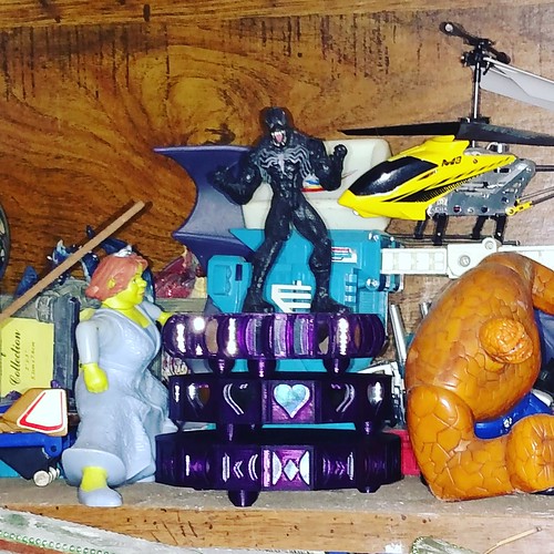
Make Your Empty Filament Spools into a Shelf
As promised, the model is up on Thingiverse as well as the original OpenSCAD code. http://www.thingiverse.com/thing:1677024
Print in Place Gyro Cube!
Wanna beta test my version of the Gyro Cube on YOUR printer? Lemme know!
I’ve led a bit of a charmed 3D Printing life. I’ve had my bobbles and frustrations, but overall, I have been floating by with relatively few worries, a happy little 3D Printing Princess without a care in the world. La la la la la.
And so it happens I have never ever done a cold-pull. Well, until recently.
I purchased a bag of used extruder/hot ends from another MakerGear owner. They arrived with eSUN Cleaner Filament in them and a note to do a cold pull when I was ready to use them.
Now, I know roughly what a cold pull is… and the term is a little self explanatory. Though one could also argue the term “sweet tea” is self explanatory as well and I thoroughly baffled a waitress in upper Michigan once with that beverage order.
When it was time to use my “new” nozzles, vaguely knowing the concept of a cold pull wasn’t going to cut it. I needed some specifics.
I unplugged the power to everything on the extruder I wanted to remove– my thermistor, the heating block, my 40mm fan, my 50mm fan.
I got out my Allen wrench and removed the fans and the filament drive.
I plugged in the thermistor and the heating block of the new nozzle. Holding it by the groove mount (I couldn’t get it in the Filament Drive until I removed the eSun filament), I used Simplify3D to heat the nozzle to 240 degrees.
Once there, I pushed the eSun filament with my hand and confirmed it was coming out of the nozzle.
Then I turned off the heat and watched the stats in Simplify3D.
I watched, waited (and regretted not having a better way to hold the nozzle) until the temperature hit 90 and then I tried to pull the filament out by hand. I actually did not succeed until the temperature hit 80 and I had some help with pliers. Then the filament pulled out and was the most lovely little, clean whisker.
Once the nozzle finished cooling, I slipped the groove mount into the filament drive and assembled everything back together (Being careful to make sure the 50mm fan goes into Fan 0 and the 40 mm fan goes into Fan 2)
And after that I checked my Z-End Stop calibration by Homing the Z-Axis and checking with a business card.
What I’ll Do Differently Next Time
So…. I had the foresight to grab a pair of needle nosed plyers with the intent of holding my hot end by the groove mount while it was hot. Know what I didn’t do? Test those plyers to make sure they’d be able to get a good grip on that rounded surface. So I ended up holding that thing with my bare hands. It was do-able.. but did get uncomfortable at times. Next time I will be better prepared. If not better plyers, then gloves. : )
As the Nova Mini Maker Faire came to a close, my demonstration print was far from done. I stopped the print, turned off and unplugged the machine, loaded the machine up into the trunk of my car, drove the 26 miles home (with a strategic stop by Burger King for some yummy yummy Chicken Fries), and set the machine back up at home. A week later, I was ready to start printing again and I wanted to start where I left off. I was able to do so with my trusy MakerGear M2 and Simplify3D. Here’s how!
Homing the Axes
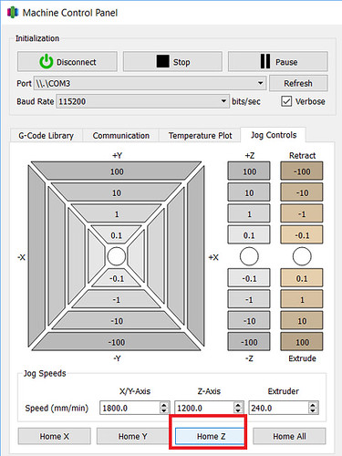
Before I could resume printing, I needed to rehome all my axes so my nozzle had all its bearings, particularly the tricky Z axis. In this case, my print was not very high, so under the Machine Control Panel in Simplify3D, I was able to move the bed around to a good spot for me to hit Home Z without my print hitting the nozzle or the X axis support bar.
Homing the Z axis can be trickier with taller prints. Since the MakerGear M2 set its Z-Endstop with a bolt on the side of the bed and it has a removable glass bed, I do have a little “hack”. When resuming taller prints, I remove the glass bed, home all the axes and then replace the bed. Sometimes there is a slight variation with the positioning of the print, but so far it has not been very noticeable in my final prints.
Where to Restart
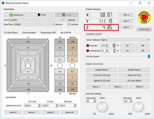
I know, I know. There are downsides to printing via the USB cable. An upside though– in Simplify3D, you have a continuous update of exactly where the nozzle is, most notably how high it is in the Z axis. In the case of my Maker Faire print, I was the one that stopped the print, so I was able to note and record the exact Z position I stopped off at. That meant I knew exactly what height I wanted to restart the print at.
Sometimes I don’t have that kind of information at my disposal. The other week, I had a filament tangle. I returned to my print to find the printer had been printing nothing for who knows how long. In those cases, I use the Jog Controls tab in the Machine Control Panel to do some sleuthing:
I start with my nozzle way above the print and I lower the Z position until I get close. The closer I get, the smaller the increments I move down, until I am using the -0.1 Z button. When I feel I am pretty much there, I pick an inconspicuous spot on the print and move the nozzle on top of it to make sure the nozzle is just barely above my print. I have found that sometimes touch is easier than sight, so I use a handy dandy business card to gauge the distance. Once I’m satisfied, I only have to refer to the positioning information in Simplify3D to get my Z startng point.
Resuming the Print
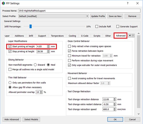
Next I tell Simplify3D where it needs to start printing. I do that under the Advanced tab and setting the Start Printing At Height setting.
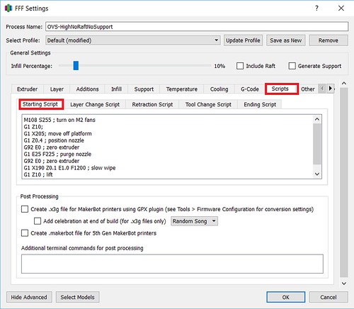
Finally, I need to give attention to my Starting Script in the Scripts tab. There are steps in the normal start up script I do not want to run. For example, I don’t want to home my axes (G28;)– I already did that manually. And depending on the object and its positioning on the bed, I may opt to alter other steps that may cause the nozzle to collide with my print. In the case of my Maker Faire print, I made some slight adjustments to the script that has the nozzle go off to the side of the bed to ooze some filament before beginning. I still wanted to do that, but I wanted to make sure the nozzle lifted up high enough (G1 Z10;) to safely cross over my object.
My normal Starting Script went from:
M108 S255 ; turn on M2 fans
G28 ; home all axes
G1 Y50 Z0.3 F9600 ; move forward to avoid binder clips
G1 X205 Z10 ; move off platform
G1 Z0.4 ; position nozzle
G92 E0 ; zero extruder
G1 E25 F225 ; purge nozzle
G92 E0 ; zero extruder
G1 X190 Z0.1 E1.0 F1200 ; slow wipe
G1 X180 Z0.25 ; lift
To
M108 S255 ; turn on M2 fans
G1 Z10;
G1 X205; move off platform
G1 Z0.4 ; position nozzle
G92 E0 ; zero extruder
G1 E25 F225 ; purge nozzle
G92 E0 ; zero extruder
G1 X190 Z0.1 E1.0 F1200 ; slow wipe
G1 Z10 ; lift
Of course, your mileage may vary, but hopefully some of this information translates or inspires a technique that works with your printer and slicer. Happy Printing!
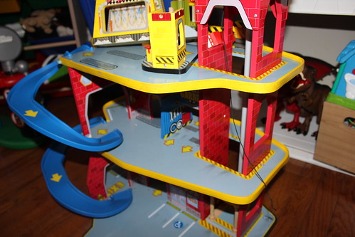
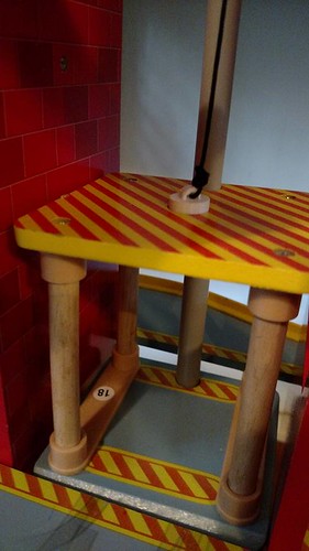
For Christmas, we got a hand-me-down KidKraft Deluxe Garage Playset.
Wonderful! There was only one minor issue– it was missing some kind of piece at the top of the elevator. As a result, the elevator did not go up and down. This caused some discontent for my two year old. At first, I would tie a toothpick at the end of the string and that would allow him to raise and lower the elevator for a while… but it frequently came undone. I thought, “Hey. I have a 3D Printer. I had TinkerCAD. I can do a lot better than a toothpick.”
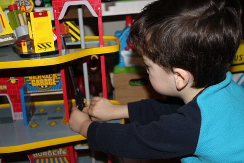
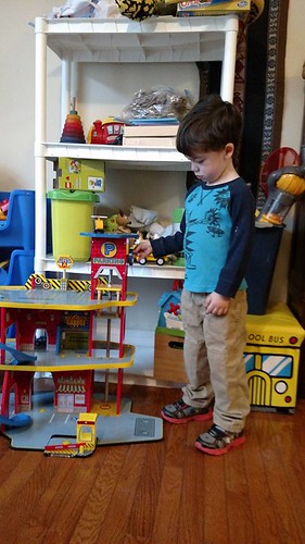
One Saturday morning, the kids and I did just that. Our first step – calipers, which both children love to play with.
I…uh…. I retook all the measurements for myself after they were done.
Then we pulled up the free and web-based TinkerCAD. As you may know, I do a great deal of modeling in Blender. I have found the colorful interface of TinkerCAD to be much more conducive to “keeping the attention of my kids.” In this case, they sat in my lap and we modeled it together.
The Model
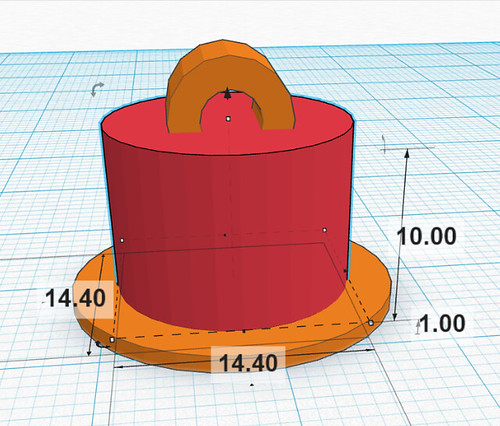
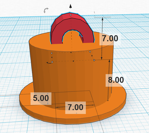
This was a very simple design. We just had three pieces:
A cylinder that I sized to the exact width of the hole we measured in the playset. Usually I put in 0.5mm clearances, but for this, I wanted a snug fit. It would even be okay if I had to force the part in.
There was also a second flat cylinder in the bottom. This was to make sure we couldn’t just pull or push the part all the way through the hole.
At the top, I used a tube. I used the Rotate handles (the little arrow icons) to rotate the tube 90 degrees.
Tip– If you hold down the Shift key while you rotate, you can rotate at 45 degree intervals.
Tip: Since I was working with exact measurements, I dragged a Ruler object to my Workplane which allows me to type in the dimensions of my parts.
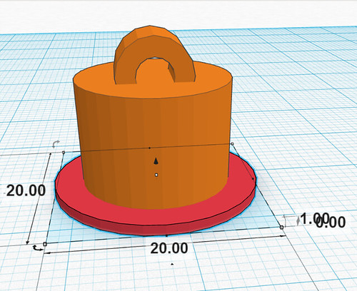
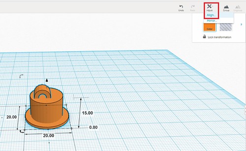
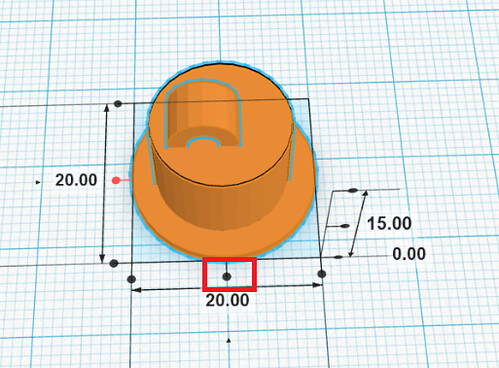
Once I had all the parts on my workplane, I selected them all and went to Adjust->Align…
This allowed me to center them all with each other.
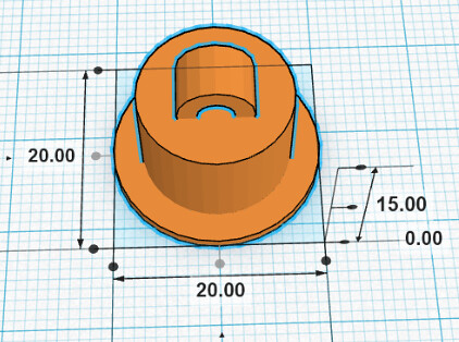
Moment of Truth
We made pancakes while the part printed and then we had a moment of truth. I was happy to discover our calipers did not lead us astray, the part fit AND the elevator worked.
Between the pancakes and this toy fix, it was a very productive Saturday morning. My Mom self esteem was at an all time high. Don’t worry– I was back to normal by the afternoon (after unsavory Mom tasks like “saying No” and “wiping butts”). : )
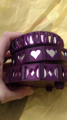
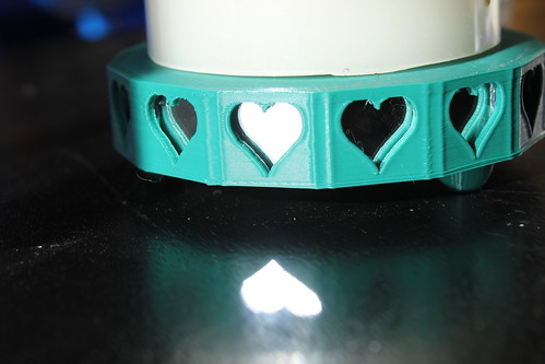
My sister turned 40 this month and get this– I have never, ever, ever printed her anything. I printed something for her husband, but not her. Bad Vicky! That definitely needed to change. Her house is a very visually stimulating house. They have a variety of lighting and effects– think blacklights, giant flatscreens with screensavers dancing to the music, lasers making patterns on the walls, lava lamps. I wanted my design to fit in and interact with the lighting in her house. I wanted something with mirrors.
Designing
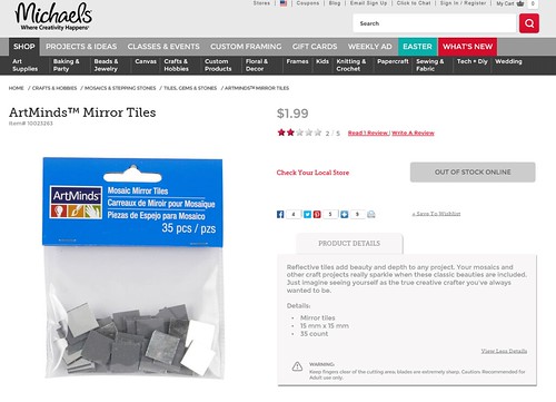
At Michael’s I bought little mosaic mirrors– 35 of them for $1.99.
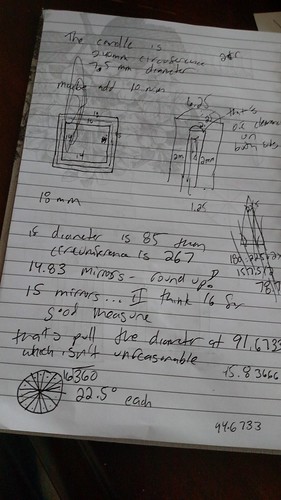
Then I got out the trusty calipers. There was some variance in the measurements, but the mirrors were pretty much 15 millimeters by 15 millimeters and 1.75 thick. I designed in cavities into my model for the placement of the mirrors. I used 0.5 millimeter clearance– which meant my “hole” came out to 16 x 16 millimeters and 2.25 thick.
All my design work was in Blender. I decided my design was going to built out of a series of 18 x 18 millimeters squares– each ready to hold a mirror. I used some simple math to figure out how many mirrors I would need to be a good stand for a 3″ pillar LED candle and the ultimate radius of my final product.
I made one template square and put in the proper placement of where it would be in the final holder. Another simple math equation told me how many degrees I would have to angle each piece.
360 degrees / # of Mirrors
So for example, in a design with 15 mirrors, each piece would be angled 24 degrees from the previous one. If I did 14 mirrors, each piece would be angled 25.714 from each other.
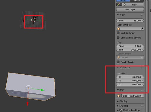
In Blender, when you rotate items, you are rotating around the Point of Origin of that object (where the little yellow dot appears when you select the Object).
Usually this is the Center of Mass of the object, but guess what! You can control it and the origin doesn’t have to be in the object itself. Once I had my template square in its proper position in the final candle holder, I placed my 3D Cursor at 0,0,0.
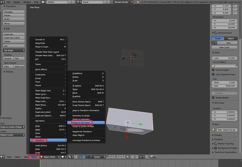
I went to Object->Transform->Origin to 3D Cursor.
This meant the origin was right smack in the middle of my candle holder. It also meant, when I rotate, I rotate around that point.
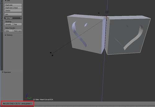
So I proceeded to Duplicate the square, hit R (for Rotate), hit Z (for around the Z axis) and then type in my angle (25.714).
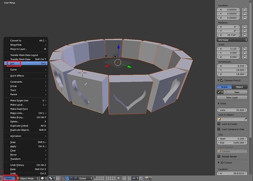
I would then Duplicate that square and Rotate it and so on until I had my entire ring. I did Object->Join to merge all my panel pieces into a single object.
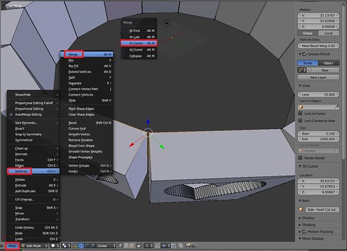
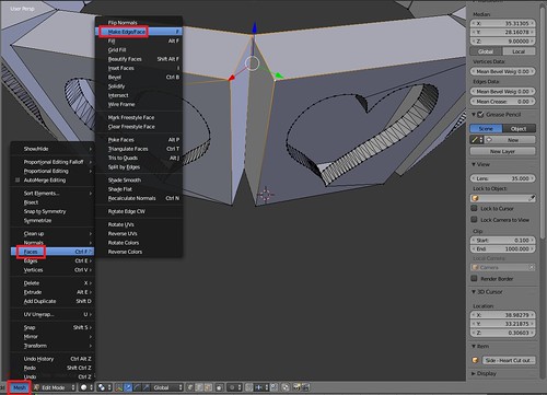
I switched to Edit mode and did some cleanup. I Merged Vertices that were close together and then added in new Faces to fill in the gap.
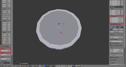
The inside of the candle holder is a 14-sided Cylinder. When you add a new Cylinder, you can specify the Number of Sides. I made it match the number of mirrors.
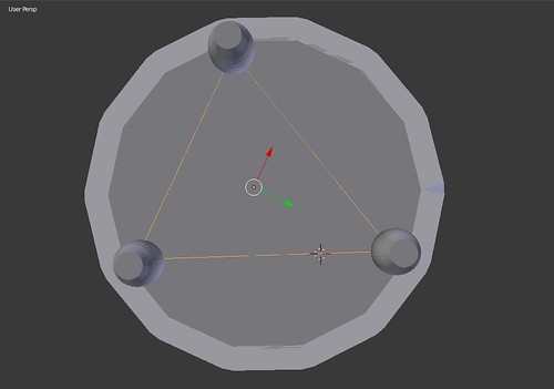
I cheated with the placement of the three feet. I added a 3-sided Circle and used that to help me determine where the place my feet.
Under Modifiers I did a Boolean Union on my panel piece, my inside cylinder and my feet and voila– I had a model!
Slicing – Simplify3D
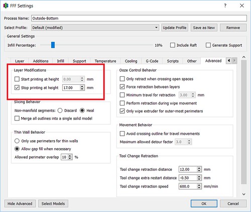
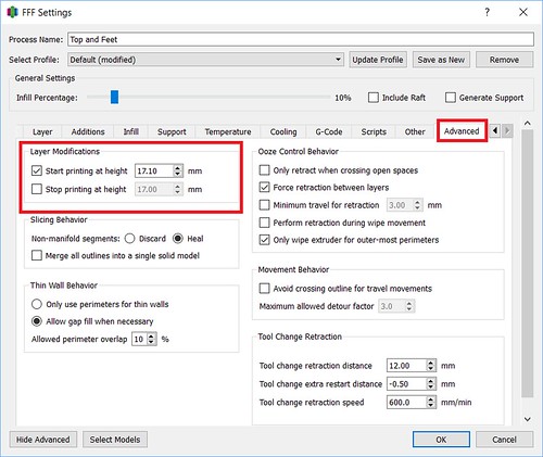
In Simplify3D, I set up two separate processes. The first process ran from the 0.00mm – 17.00mm (You can set that up in the Advanced tab under Layer Modifications). That is the point right before my mirror cavities would get sealed up.
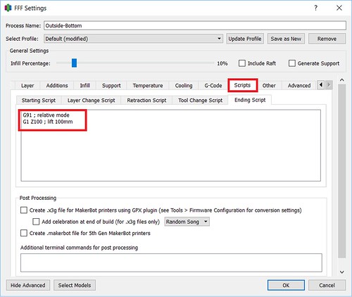
Usually when a process finishes, it’ll run a default ending process– turning off the extruder and disabling the motors, completely dropping the bed. I didn’t want that to happen. In this case, I just wanted the bed to drop down enough for me to put those mirrors in without burning myself and more importantly, get that hot nozzle off my print so it isn’t melting and deforming it and making it hard for me to slide my mirrors in. I went under Scripts and customized my Ending Script. Instead of the usual process, I did two simple steps:
1) I changed it to Relative mode, so my next instruction would use the nozzle’s current position as it’s starting point
2) I told it to move the nozzle up 100mm.
G91 ; relative mode
G1 Z100 ; lift 100mm
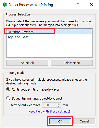
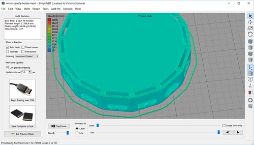
When I prepared just that process for printing, you could see how it was going to stop while I still had openings for my mirrors.
My second process was set up to run from 17.10mm on (again under the Advanced tab)
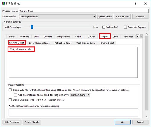
When a process begins, there are a number of things the printer typically does at the beginning such as turning on the extruder, turning on the fans, homing the axis’s, running off the side of the bed and oozing some filament. I didn’t want to do this for my second process. My axis’s are already homed, my extruder is already heated up, my filament is already flowing. All I had to do was set my printer back to Absolute mode and go. So for this second process, I went under Scripts and customized the Starting Script.
G90 ; absolute mode
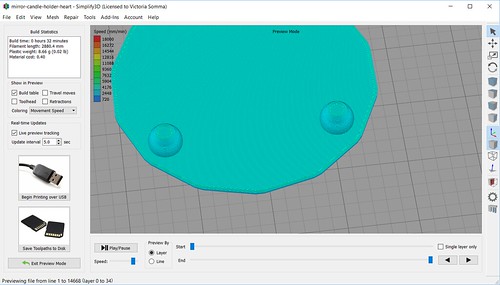
A preview of the second process, illustrates how the mirrors will get sealed in by the print.
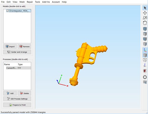
After a recent trip the Air and Space Museum’s Udvar-Hazy Center, my husband had a 3D Printing request for me. He wanted a 1934 Buck Rogers Disintegrator Gun.
The Model
Thanks to the great community up on Thingiverse, I didn’t have to do any modeling. I had THREE Buck Rogers Guns to choose from. The one that caught my eye and seemed to most resemble what my husband wanted was “Disintegrator 1934 Buck Rogers Gun” by user bluesroq.
The designer recommended printing the model with supports and there is indeed a lot of overhangs with how the gun is positioning now.
Avoiding Supports
Even though Simplify3D has top notch supports that are easy to remove and easy to control, I wanted to try to avoid supports in this case for a few reasons:
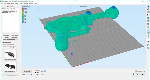
As great as Simplify3D supports are, they would still leave some scarring or souvenirs on the faces– in this case– an entire side of my gun would be subject to that and not look as pretty and finished as the other side.
Supports increase your printing time AND your material usage. In the case of an adult-sized Buck Rogers gun, the print time would have gone from 4 hours 30 minutes to 7 hours 12 minutes!
If it were in half, this particular model would be an easy, straight forward print without any troubling overhangs.
Looking over the Buck Rogers Gun, the model itself was very symmetrical. It would be a great model to print in two halves and glue together. As a 3D Modeler, I could easily pull this model into something like Blender and break in half that way. But, I could also save time and just do it through my slicer! : )
Cutting in Half – Simplify3D
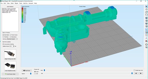
In Simplify3D, anything that is below your build plate will get ignored by the printer. So in the case of this gun, I would want to lower it down so half of it is above the build plate and half is below. The steps would be:
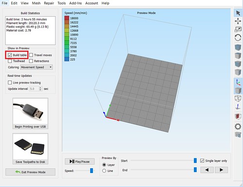
First off, it is helpful to see the build plate while you are working. If yours is not displaying in your Simplify3D, click on Prepare to Print and check the Build Table under Show In Preview.
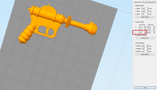
Next we need to figure out how far we want to lower our model. Simplify3D makes that easy for us as well. Double click on your model and in the information panel under the Change Scaling section, we will get a reference of the exact measurements. In this case, we are interested in the height of the model, the Z value.
Now we have some simple math. We want to lower the model so only half of it is above the print bed. That means we want to divide the height by 2. In this example– 25.43 divided by 2 is 12.71. In our Change Position section, we want to change the Z offset to -12.71 (aka Lower the model 12.71 mm).
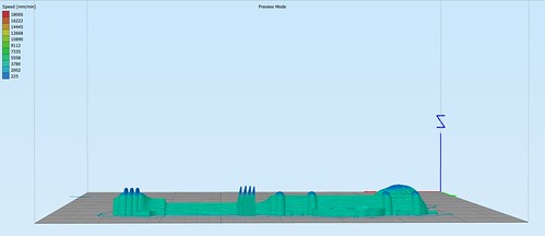
At this point, half of our model is under the print bed! If we click on Prepare to Print, you’ll see that only half of the model is going to be printed.
Getting the Second Half – Simplify3D
To make a whole gun, we obviously want to print two halves of the gun.
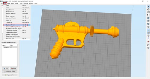
Click on your model to select it and then go to Edit->Duplicate Models and make one more copy. You may have to move it around to a better spot on the build plate. (You can also click on the Center and Arrange— but you’ll have to reset your Z Offset again for the original model).
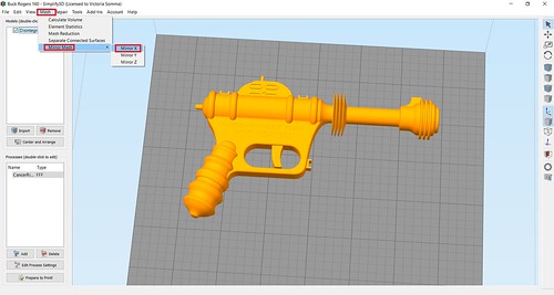
Now we have to flip our new part. Gotcha– Watch Out for Mirroring! My first inclination was to go Mesh->Mirror Mesh and mirror my second half over the X or the Y axis. That could work for some models, but in the case where there is text on your model (like this), then that also mirrors your text and it too would be backwards. Mirroring should also be avoided if your model isn’t exactly symmetrical and has different detailings on each side.
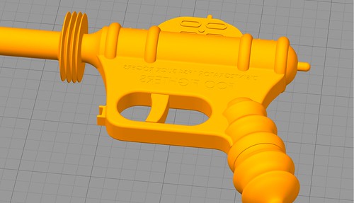
D’oh – Backwards Text
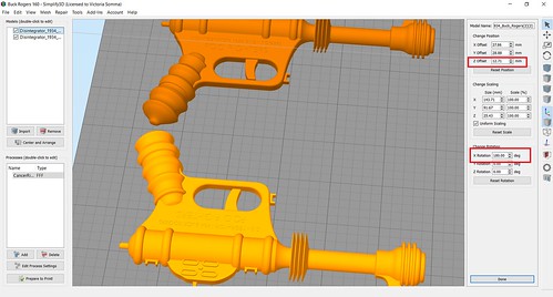
In lieu of mirroring, you can rotate it! Double click the object and then in the Change Rotation section, rotate the model 180 over the X or Y axis. Don’t be alarmed if your object suddenly “disappears”. It’s actually underneath your print bed. You just have to adjust the Z Offset now to move the new one 12.71 above the print bed.
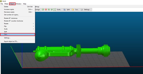
Slic3r
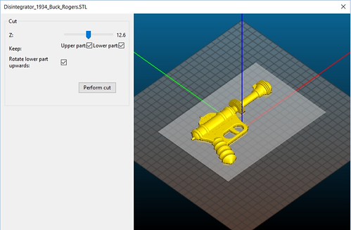
I have found Simplify3D to be absolutely 100% worth my money, but if it is not for you or your budget, you are not out of luck. You may be able to do the same thing in your slicer. As an example in open-sourced (and free) Slic3r, once you had your object on your plater, you would go to Object->Cut…
And you can pick the cutting height (and you have options to get both sides and rotate one)
And there you go, you can break your model up without modeling software like Blender. This technique’s applications are not limited to merely cutting objects in half. You can use it anytime you want to isolate out a particular section of a model to print. Say you got a 3D Hubs order and you are worried about a tricky section near the top. You don’t have to waste the time and material to run the whole print to find out that section is going to fail. Instead, you can lower your object down and do a quick print on just the troublesome section to see how it performs.