Category Archives: 3D Modeling

My Model at CES!!!

Well a hat tip to the impressively, eagle-eyed Joel Telling for noticing this. One of my models, the Spinning PokeStop Ornament, was one of the showcase prints at a booth at CES. I’m not sure if they followed the attribution clause of my Creative Commons Licensing…. but I’m still excited that a model of mine was used.

Slides for 3D Printing and Crafts Presentation

Last Thursday night, I had the delight of participating in a Meetup with the Delaware 3D Printing Group. The event was hosted by Printed Solid. The group was kind enough to let me yammer on about my 3D Printed Crafts. 🙂 I very much enjoyed chatting with other printing enthusiasts and left the event invigorated. I should make it a point to do an event like this every November when the fatigue that accompanies Cyber Week looms in my brain. 🙂

For those who missed it, I do have all my slides up on SlideShare.

Using Inkscape and Tinkercad to Customize Halloween Pendants

HAPPY HALLOWEEN!

My very first Thingiverse upload was glowing pumpkin pendants/pins for kids.  This video hits briefly on how I print these via Multi-processes in Simplify3D (Spoiler alert – they are three separate prints).  It will also show you how you can import in the pendant template into TinkerCAD and quickly make your own customizations.  Finally, have a drawing you want to use?  I’ll go over using Inkscape to make a SVG file from a black and white image/photo/scan that you can also pull into TinkerCAD to “carve” your pumpkin.
All the pumpkin models, including the template are up on Thingiverse at:
http://www.thingiverse.com/thing:1074202
Need help with Simplify3D Multiple Processes?  I learned from THIS Joel Telling video:
https://youtu.be/ZHe2_h1nQG4
TinkerCAD is free with nothing to install– http://www.tinkercad.com
Finally, Inkscape is also free and can be downloaded at http://www.inkscape.org.
The Starting and Stopping Points of My Processes
0 – 1.5mm – Black or Green
1.5 – 2mm – GlowFill
2mm – rest – Orange

What in the World Has Vicky Been Up To?!!?

I’m back with 3D Printings after a bit of a hiatus and I have a lot to catch you up on!

Printed Solid Grand Opening!
A freaking wonderful, invigorating event. Joel Telling’s overview of the event can be found at https://www.youtube.com/watch?v=qnZqMnokjpw

What does TGAW stand for? That is answered in Joel’s interview with me:
https://www.youtube.com/watch?v=REvIWbER_Gc

Anglerfish
Blog post with more details on the creation of my bronzeFill/GlowFill Anglerfish. I do have one more if you happen to covet one. 😉
http://tgaw.com/wp/?p=307

Bow Ties!
I’ll work on a video about their design in Blender and the attachment design in OpenSCAD. It’ll use words like “Texture”, “Baking”, “Displacement Maps” and “Boolean Intersection”. In the meantime, I do have some listed on Etsy at https://www.etsy.com/shop/VickyTGAW

Land’s End Gazebo
The real live gazebo in Sayville, NY can be found here http://www.landsendweddings.com/

Geocoin
Check out the AMAZING family I am designing for. You couldn’t get better inspiration than that!
https://www.youtube.com/watch?v=znnSSlJF79w

Make Your Empty Filament Spools into a Shelf
As promised, the model is up on Thingiverse as well as the original OpenSCAD code.
http://www.thingiverse.com/thing:1677024

Print in Place Gyro Cube!
Wanna beta test my version of the Gyro Cube on YOUR printer? Lemme know!

Thanks for watching! Happy Printing!

Fixing a KidKraft Deluxe Garage Playset with Tinkercad!


Watch or Listen to This Blog Post Above

For Christmas, we got a hand-me-down KidKraft Deluxe Garage Playset.

3D Printing - Elevator Fix - KidKraft Deluxe Garage Playset

Wonderful! There was only one minor issue– it was missing some kind of piece at the top of the elevator. As a result, the elevator did not go up and down. This caused some discontent for my two year old. At first, I would tie a toothpick at the end of the string and that would allow him to raise and lower the elevator for a while… but it frequently came undone. I thought, “Hey. I have a 3D Printer. I had TinkerCAD. I can do a lot better than a toothpick.”

One Saturday morning, the kids and I did just that. Our first step – calipers, which both children love to play with.

3D Printing - Elevator Fix - Calipers

I…uh…. I retook all the measurements for myself after they were done.

Then we pulled up the free and web-based TinkerCAD. As you may know, I do a great deal of modeling in Blender. I have found the colorful interface of TinkerCAD to be much more conducive to “keeping the attention of my kids.” In this case, they sat in my lap and we modeled it together.

The Model
This was a very simple design. We just had three pieces:

  1. A cylinder that I sized to the exact width of the hole we measured in the playset. Usually I put in 0.5mm clearances, but for this, I wanted a snug fit. It would even be okay if I had to force the part in.
    MainBarrell
  2. There was also a second flat cylinder in the bottom. This was to make sure we couldn’t just pull or push the part all the way through the hole.

    StopperCylinder

  3. At the top, I used a tube. I used the Rotate handles (the little arrow icons) to rotate the tube 90 degrees.

    Tip– If you hold down the Shift key while you rotate, you can rotate at 45 degree intervals.

    Hook

Tip: Since I was working with exact measurements, I dragged a Ruler object to my Workplane which allows me to type in the dimensions of my parts.

Once I had all the parts on my workplane, I selected them all and went to Adjust->Align…

Adjust Align

This allowed me to center them all with each other.

Aligning

AlignAfter

Moment of Truth
We made pancakes while the part printed and then we had a moment of truth. I was happy to discover our calipers did not lead us astray, the part fit AND the elevator worked.

InstalledPiece

SaganUsingElevator

Between the pancakes and this toy fix, it was a very productive Saturday morning. My Mom self esteem was at an all time high. Don’t worry– I was back to normal by the afternoon (after unsavory Mom tasks like “saying No” and “wiping butts”). : )

P.S. If you happen to have a KidKraft Deluxe Garage Playset in the need of the same part, it is free for download and use on TinkerCAD!

Embedding Mirrors Into Prints with Simplify3D

My sister turned 40 this month and get this– I have never, ever, ever printed her anything. I printed something for her husband, but not her. Bad Vicky! That definitely needed to change. Her house is a very visually stimulating house. They have a variety of lighting and effects– think blacklights, giant flatscreens with screensavers dancing to the music, lasers making patterns on the walls, lava lamps. I wanted my design to fit in and interact with the lighting in her house. I wanted something with mirrors.

Designing
At Michael’s I bought little mosaic mirrors– 35 of them for $1.99.

3D Printing Mosiac Mirror Tiles

Then I got out the trusty calipers. There was some variance in the measurements, but the mirrors were pretty much 15 millimeters by 15 millimeters and 1.75 thick. I designed in cavities into my model for the placement of the mirrors. I used 0.5 millimeter clearance– which meant my “hole” came out to 16 x 16 millimeters and 2.25 thick.

All my design work was in Blender. I decided my design was going to built out of a series of 18 x 18 millimeters squares– each ready to hold a mirror. I used some simple math to figure out how many mirrors I would need to be a good stand for a 3″ pillar LED candle and the ultimate radius of my final product.

3D Printing - MATH!

I made one template square and put in the proper placement of where it would be in the final holder. Another simple math equation told me how many degrees I would have to angle each piece.

360 degrees / # of Mirrors

So for example, in a design with 15 mirrors, each piece would be angled 24 degrees from the previous one. If I did 14 mirrors, each piece would be angled 25.714 from each other.

In Blender, when you rotate items, you are rotating around the Point of Origin of that object (where the little yellow dot appears when you select the Object).

Usually this is the Center of Mass of the object, but guess what! You can control it and the origin doesn’t have to be in the object itself. Once I had my template square in its proper position in the final candle holder, I placed my 3D Cursor at 0,0,0.

Blender - Setting 3D Cursor

I went to Object->Transform->Origin to 3D Cursor.

Blender - Origin to 3D Cursor

This meant the origin was right smack in the middle of my candle holder. It also meant, when I rotate, I rotate around that point.

So I proceeded to Duplicate the square, hit R (for Rotate), hit Z (for around the Z axis) and then type in my angle (25.714).

Blender - Rotate 25.714 along Z Axis

I would then Duplicate that square and Rotate it and so on until I had my entire ring. I did Object->Join to merge all my panel pieces into a single object.

Blender - Object Join

I switched to Edit mode and did some cleanup. I Merged Vertices that were close together and then added in new Faces to fill in the gap.

Blender - Vertices Cleanup

Blender - Filler Faces

The inside of the candle holder is a 14-sided Cylinder. When you add a new Cylinder, you can specify the Number of Sides. I made it match the number of mirrors.

Blender - Inside Cylinder - 14 Sides

I cheated with the placement of the three feet. I added a 3-sided Circle and used that to help me determine where the place my feet.

Blender - 3D Sided Circle To Help with Foot Placement

Under Modifiers I did a Boolean Union on my panel piece, my inside cylinder and my feet and voila– I had a model!

Slicing – Simplify3D
In Simplify3D, I set up two separate processes. The first process ran from the 0.00mm – 17.00mm (You can set that up in the Advanced tab under Layer Modifications). That is the point right before my mirror cavities would get sealed up.

3D Printing with Mirrors - Simplify 3D - Layer Modification Settings for the Bottom

Usually when a process finishes, it’ll run a default ending process– turning off the extruder and disabling the motors, completely dropping the bed. I didn’t want that to happen. In this case, I just wanted the bed to drop down enough for me to put those mirrors in without burning myself and more importantly, get that hot nozzle off my print so it isn’t melting and deforming it and making it hard for me to slide my mirrors in. I went under Scripts and customized my Ending Script. Instead of the usual process, I did two simple steps:

1) I changed it to Relative mode, so my next instruction would use the nozzle’s current position as it’s starting point
2) I told it to move the nozzle up 100mm.

G91 ; relative mode
G1 Z100 ; lift 100mm

3D Printing with Mirrors - Simplify 3D - Ending Script for Bottom

When I prepared just that process for printing, you could see how it was going to stop while I still had openings for my mirrors.

3D Printing with Mirrors - Simplify 3D - Selecting the First Process

3D Printing with Mirrors - Simplify 3D - Preview of First Process

My second process was set up to run from 17.10mm on (again under the Advanced tab)
3D Printing with Mirrors - Simplify 3D - Layer Modification Settings for the Second Process

When a process begins, there are a number of things the printer typically does at the beginning such as turning on the extruder, turning on the fans, homing the axis’s, running off the side of the bed and oozing some filament. I didn’t want to do this for my second process. My axis’s are already homed, my extruder is already heated up, my filament is already flowing. All I had to do was set my printer back to Absolute mode and go. So for this second process, I went under Scripts and customized the Starting Script.

G90 ; absolute mode

3D Printing with Mirrors - Simplify 3D - Starting Script for Second Process

A preview of the second process, illustrates how the mirrors will get sealed in by the print.

3D Printing with Mirrors - Simplify 3D - Preview of Second Process

The process worked out fantastically (Watch it in Action in the YouTube video above– starting at about 7 minutes in).

All in all I did three different designs for my sister.

3D Printing - Embedding Mirrors in Prints

I loved the final product so much I had to make another for myself.

3D Printing with Embedded Mirrors - Heart and Reflection

They ended up looking fantastic stacked. My sister used them as a platform for her Venom action figure. : )

3D Printing - Venon is Victorious on the Mirrored Candle Holders

Personalized Glowing Valentines for Kids

My son is named Sagan, after Carl Sagan.  Over here in the U.S., that’s a unique name.  As a result, he won’t be going into gas stations or souvenir shops and finding mass produced keychains and trinkets with his name on it.

Luckily, I have the MakerGear M2. I am not bound to get what someone else has decided to design and make.  I can make it myself!

3D Printing Valentines - Sagan

In my son’s pre-K class, a vast majority of the students are in the same boat– most of them have unique names. This seemed like a great use for the flexibility of a 3D Printer.

The Design
The design is not especially ground breaking. Hey, it’s a little heart pendant/medallion with a name on it. I printed most of it in ColorFabb Traffic Red PLA/PHA (duh) and then the detailing and the name are in GlowFill. One thing I have noticed with my kids is they LOVE glowing things. They love taking it into the bathroom and turning off the lights to see it glow.

Glowing Valentines

Modeling – Blender
The base model I did in Blender. I started with a Bezier Curve. I used the Mirror modifier to make it symmetrical.

Modeling a Heart - Bezier Curve - Mirror

I converted the curve to a Mesh. Modeling a Heart - Convert to Object

I did a little cleanup of the Vertices, by Merging a couple of oddly mirrored vertices to the center.
Modeling a Heart - Merge Vertices at Center

The detailing of my design, I wanted an outline of a heart in GlowFill. I’ve worked with hearts in the past and I knew that just scaling another heart down wasn’t going to do the trick. Inset is key to that!
MOdeling a Heart - Scale VersusInset
Scaling Versus Inset – Inset Will Give You Consistent Widths

I did an Inset of my face and did some manual cleanup of the vertices.

After that, it was just straight Extrusion to the heights I wanted.

The hook was just a cylinder subtracted from another cylinder (courtesy of the Boolean Modifier). I decided to keep the hook separate in case anyone wanted to print just straight up hearts.

At the end of my Blender session– I had two .STL files — my heart and my hook to make it a medallion.

Modeling – OpenSCAD
Although I had experimented with Python scripting for Blender roughly a year ago, OpenSCAD seemed easier and quicker for me. There is an Import command in OpenSCAD where you can pull in STL files. I went ahead and brought my Blender STL files into my OpenSCAD project and set a variable name for the “Child’s Name”. I was then able to rapidly run through and create 17 models for all my son’s classmates.

child_name = "Adela";
font_size=10;
y_offset=-4;

union()
{
 translate([30,10,0])
   import("heart.stl", convexity=10);

  
 translate([30,10,0])
  import("hook.stl", convexity=10);  


translate([30,y_offset,2])
linear_extrude(height=0.7)
    text(child_name, halign="center", size=font_size);
}


Slicing and Printing – Simplify3D and MakerGear M2
I printed on my trusty MakerGear M2. Since I have a single extruder machine, I used Simplify3D to set up two processes to print my heart:

Red
From 0.0 – 1.0mm, I printed in ColorFabb Traffic Red PLA/PHA. I printed in 0.25mm layer heights.
Slicing a Heart - First Process in Simplify3D

GlowFill
From 1.1 – 1.7mm, I printed in ColorFabb GlowFill. I printed those in 0.10mm heights. Usually I have found with detailing 3 or 4 layers were sufficient. In this case, because the GlowFill was a little translucent, going up to 6 and 7 layers made sure the text appeared more crisp and white. (It also gave me a little more leeway to recover if an edge came unstuck from the build plate).
Slicing a Heart - Second Process in Simplify3D

Quick Tip
And a quick tip. Sometimes parenting is harder than 3D Printing. When I printed my first batch of hearts, I was quite pleased. I showed my son and was ready for a positive response. It did not go well. I..uh… I kinda didn’t include his name in the first batch of hearts. He can read and he was quite miffed when he did not see his name. Luckily, I started an emergency print and was able to get back on his good side. But you can avoid such drama. Make sure to print your kids’ in the first batch. : )

Forgiven

On Thingiverse!
If you covet a heart for Valentine’s Day or a special occasion, I was able to make a Customizer on Thingiverse. Feel free to make your own.

Modeling Diary – Occoquan’s Mill House Museum

After the Occoquan Arts and Craft Fair, I was approached by the Occoquan Business Guild. This holiday season the Virginia Governor’s Mansion is celebrating Virginia’s localities. They invited counties, cities, and towns throughout the state to design an ornament for tree. I was asked to design the Christmas Ornament representing Occoquan!

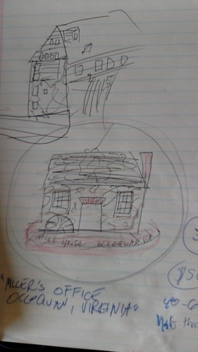
Originally we discussed a replica of the old Ellicott Mill which was the very first automated mill in Virginia. But, the Mill looked to be particularly ambitious in the timeframe (end of October). So we ultimately decided to do an ornament based on the Mill House, which is a structure that still stands today and is home to Occoquan’s Mill House Museum. The Mill House’s shape seemed like it would aesthetically make a better ornament.

This structure also has an emotional connection to me and my family. My maternal grandmother worked at the Mill House Museum for many years.

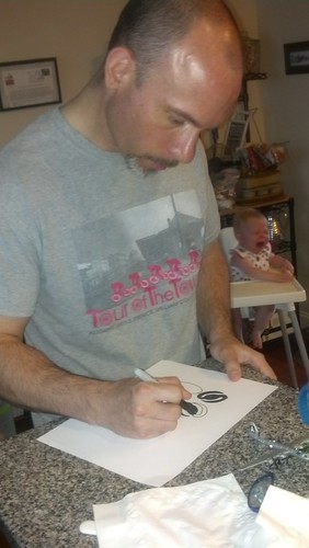
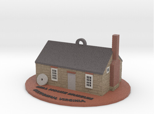
I did some sketches and settled on a pretty literal translation of the Mill House. Since the Mill House is a stone structure, I recommended the final print be in Shapeways’ Full Color Sandstone. I felt its stone-like finish would be perfect for the ornament.

3D Printing - Mill House Museum  Original Sketch

Modeling – Base Structure and Details
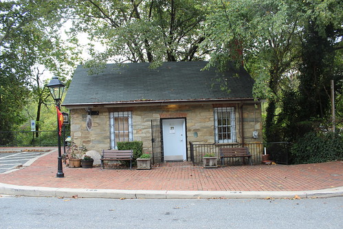
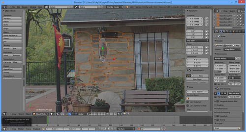
For modeling, I used some reference photos I took of the building.

Mill House Reference - Front

Mill House Reference - Mill Side

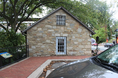
The side of the mill with the chimney was tight for me to get pictures, so for that side I also used a reference photo I took of a model by former Council Member Dr. Walbert.

SMALL Mill House - Chimney Referene

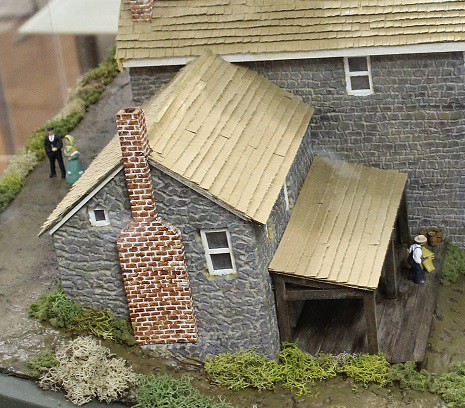
One of the key features I wanted on the ornament was an old Mill Stone laying on the building. For that, I referred to good ole Wikipedia and its article on millstones!

Modeling – Mill House
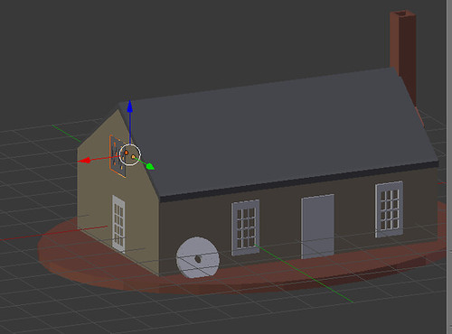
I did all my work in the free modeling software Blender. The base model, the windows, the door, the brick trim above the windows and the chimney shape all went quickly and were pretty much done with cubes and basic mesh modeling.

3D Printing - Occoquan Mill House Museum -Mill House Start

Modeling – Physical Textures
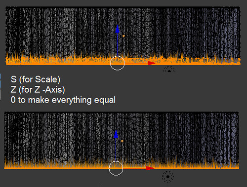
And then I had the tricky part. The stone work and the brick work. Now, because we were planning on Full Color Sandstone, I did have the option of doing a UV Map and doing that details just through the colors. But I decided, I really wanted those textures to be actual textures. If we wanted to print the model in bronzeFill or plastic, I wanted the details to translate. I briefly researched Displacement Maps, but with the time clock ticking, I went with an approach I was more comfortable with. (One day I may look back and think, “Dude- you did this the HARD way!”)

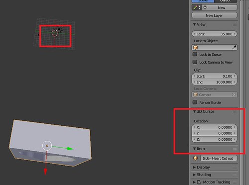
All my physical textures I went with a height of 0.5mm. I have found 0.5mm details look good on my MakerGear M2– it’s big enough for the detail to be distinctive, but small enough that the printer doesn’t struggle with overhangs.

Modeling – Bricks
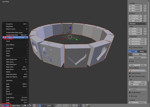
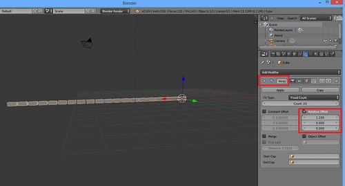
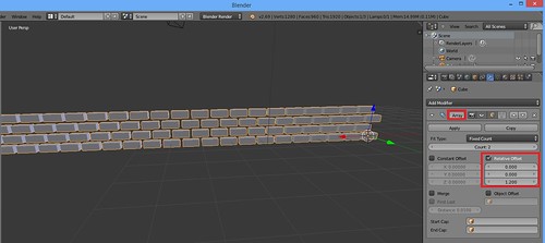
Bricks– I made a small cube as a brick and then used the Array Modifier to make a line of evenly spaced bricks.

3D Printing - Occoquan Mill House Museum -Screenshot - Brickwork

After I applied that Array Modifier, I did another! I made one row and offset it a little bit to get the stratified effect of two rows of bricks.

3D Printing - Occoquan Mill House Museum -Screenshot - Brickwork 2

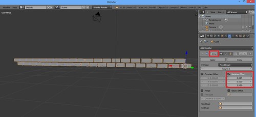
Finally I used the Array Modifier one more time to make a big sheet of bricks!

3D Printing - Occoquan Mill House Museum -Screenshot - Brickwork 3

Modeling – Stones
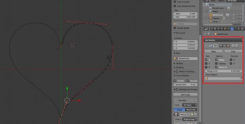
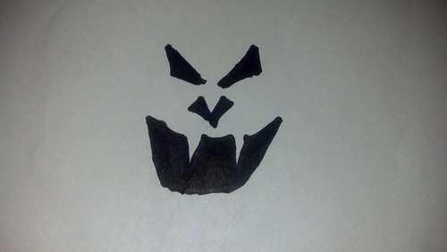
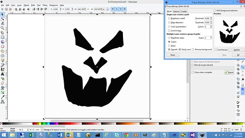
For the stone work, I was partially a purist. I pulled up a new Blender project and traced out some of the real stones of the Mill House in Bezier Curves. And once I had a good selection, I used that mini sheet of stones to make bigger sheets.

3D Printing - Occoquan Mill House Museum -Screenshot - Stone Work

Modeling – Fitting the Brick and Stonework
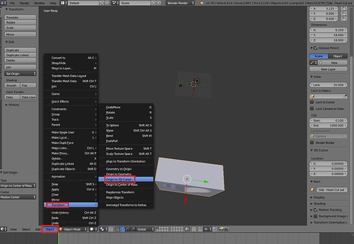
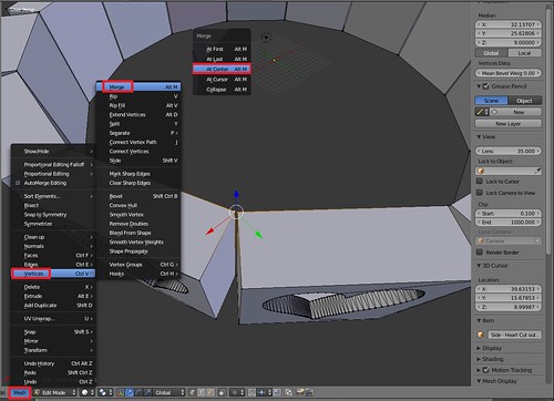
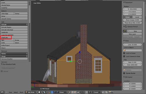
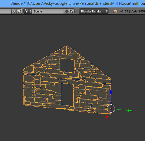
To fit my stonework and brick work to the actual Mill House, I made little templates of the sides I wanted to work with. I started by making a template of the side I wanted the texture for. This would include window and detail cut outs where I did not want stone or brick. This took me a while to find a process I liked. I finally ended up with ended duplicating any pertinent vertices.

3D Printing - Mill House - Duplicate Vertices

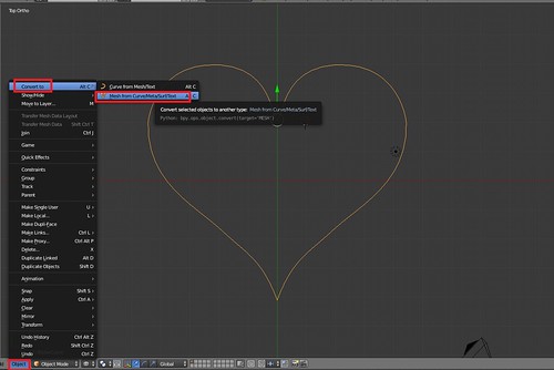
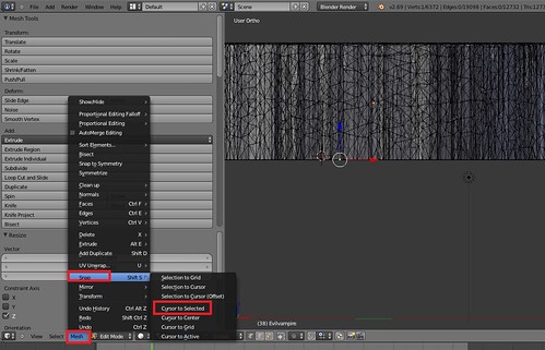
Then I separated them into their own object by going to Mesh->Vertices->Separate->Selection.

3D Printing - Mill House - Seperate Vertices

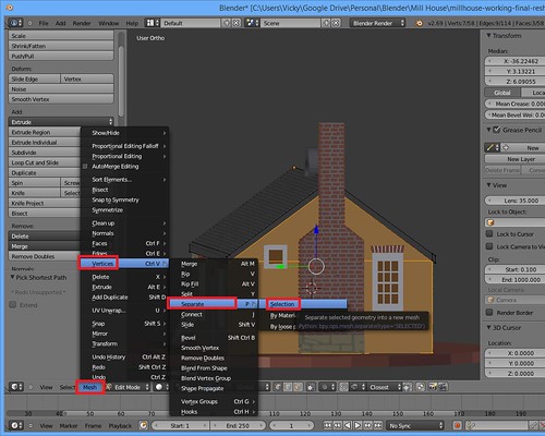
I sometimes had to repeat with other objects (such as windows).

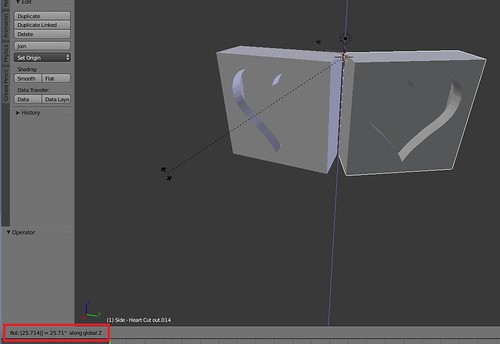
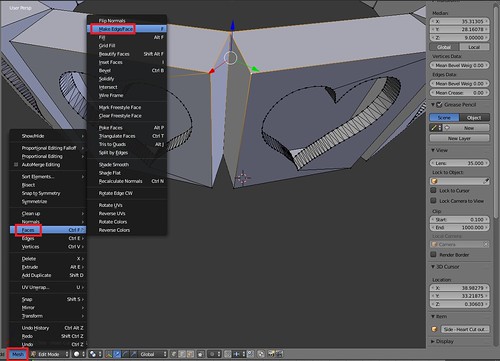
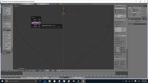
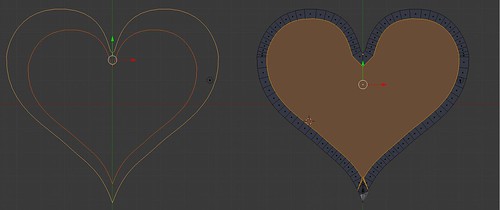
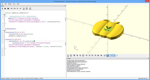
Once I had all the relevant vertices, I made a new face of what I wanted stonework for. From there, I used the Boolean Modifier and Intersection to cut my sheet of stonework into…a specifically shaped sheet of stonework.

3D Printing - Occoquan Mill House Museum -Screenshot - Intersection

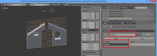
And I ended up with my final textured piece that I could overlay over my Mill House.

3D Printing - Occoquan Mill House Museum -Screenshot - Intersection Aftermath

Modeling – Colors
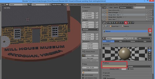
With the Mill House, I didn’t have to create a UV Map for my coloring. I was able to do it all by the Materials tab for my objects.

3D Printing - Occoquan Mill House Museum -Colors

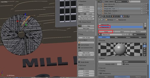
In a couple of spots, I assigned a different material to specific faces (like grooves in the Mill Stone)

3D Printing - Occoquan Mill House Museum -Color Faces

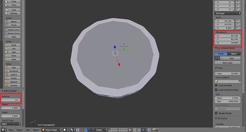
Modeling – Hollowing
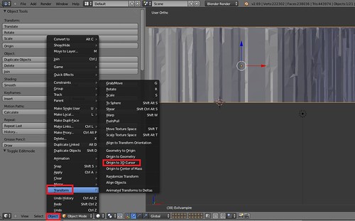
To save on material cost I did hollow out my Mill House. It was an easy process– I Inset the bottom face and Extruded up.

Renders and Rework
Originally I did my shingles with an Subdivide, Inset and Extrude technique. It looked fabulous in my Mamie Davis Gazebo Ornament, but I did not like it in my Mill House renders.

3D Printing - Occoquan Mill House Museum - Sandstone Render

I went back and redid the shingles the way I did the bricks (so they were staggered).

3D Printing - Occoquan Mill House Museum - Sandstone Render - New Shingles

I met with my contacts and gave them a tour of the model and the renders and they loved it! The only tweak they had was to add a doorknob.

“That’s it!” I yelled enthusiastically!

The door had been bothering me all week. It just did not look right. As soon as they said doorknob– I knew that was it. That was the missing piece.
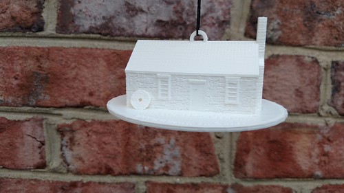
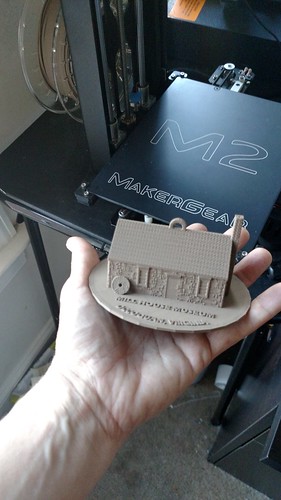
3D Printing - Occoquan Mill House Museum - Reshingled - Final

Test Prints
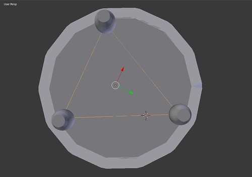
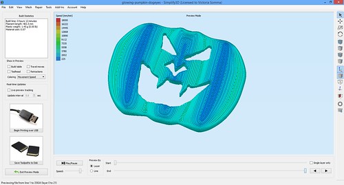
One of my concerns was the balance of the ornament would be off or that once printed, I wouldn’t be fond of the size I chose. So I did a test print on the Maker Gear M2. And….. I was in love. Even though my printer did not pick up the window panes and I noticed a few minor issues, I was impressed at how great all the detailing came out on my printer. I am so glad I went to the trouble to make that stonework and brick work physical details instead of just colors. As for balance– it balanced perfectly!

3D Printing - Occoquan's Mill House Museum - Test Print in White - It Balances

And for fun, I also did a version for myself in ColorFabb bronzeFill.
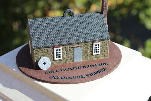
3D Printing - BronzeFill Mill House Museum From the M2

Final Print
My final print came out a little darker than I expected, but still very identifable as the Mill House. The most important part– the “customer” was thrilled! Phew!

Mill House - Top

And Now…
And now the ornament makes it way to the Virginia Governor’s Mansion! Exciting!

Carving My Pumpkins In Blender

We’ve done a number of faces now for my Glowing Pumpkin Pendants for the Fall Occoquan Arts and Craft Show. I thought I would go ahead and document my carving process in Blender.

Quick background– with the pumpkins, I print 1.5mm of ColorFabb Green. I next switch over the ColorFabb GlowFill for another 1mm. Finally, I end with Translucent Orange filament from MakerGear.

Cross Section of Pumpkin

What this all means is whatever face I’m using to carve out of my pumpkin template (be it through OpenSCAD, Inkscape, ShapeJS, or any other means)– I want the bottom to be right at the 2.5 mm mark. I want the hole to extend all the way down through the orange to the top of my GlowFill.

Although, not intuitive, this is pretty easy in Blender.

First I import my face (in .STL format) from the File->Import menu option. If necessary, I resize it to fit more appropriately on the pumpkin. Now the fun part– what’s the easiest way for me to make sure my face carving goes all the way to the 2.5mm mark?

  1. I switch to Edit mode.
  2. I click on one of the vertices that is at the bottom of my face.
  3. I go to Mesh->Snap->Cursor to Selected
    Blender - Positioning
    This moves my 3D cursor to that selected vertex.
  4. I switch to Object mode
  5. I go to Object->Transform->Origin to 3D Cursor
    Blender - Changing Origin
    This makes the point of reference for that object that very same vertex. This means when I am filling in coordinates for that object, it is using that vertex for the placement.
  6. Finally, at this point, I just change the Z position of my object (assuming I’m on Global) to 2.5mm.

    Blender - Setting Exact Coordinates

And there you have it— the bottom of my face I wish to carve out of the pumpkin is down at the 2.5mm mark, the top of my GlowFill layer. At this point, I can proceed with going to the Modifiers, adding a Boolean modifier and doing a Difference Operation on my pumpkin template and my face. (The difference allows me to subtract an object from another object).

Just to be sure, I do double check in Simplify3D that my orange process looks we expected. In particular, I don’t want to see a solid layer of orange covering up my GlowFill.

Simplify3D - Previewing Orange Layers

I haven’t had any trouble with ShapeJS and my Black and White PNG images. However, if I were ever to be concerned my pumpkin face did not have an even bottom, I could make sure the bottom was consistent by:

  1. Go into Edit mode
  2. Select all the vertices on the bottom of my face (I typically take advantage of Select->Border Select)
  3. Hit S (for Scale) and then Z for the Z-axis and then 0. This sets ALL the selected vertices to the exact same Z height, so I’m thoroughly ensured if one vertex is at 2.5mm, they all are.
    Blender - S Z 0

And there you have it— how I carve my pumpkins (for now).

Print Diary – Experiments in Pumpkin Carvings

Occoquan Arts and Craft Show – September 26th and 27th!
First off, I’m in! My application to the Fall Occoquan Arts and Crafts Show has been accepted (with multiple explanation marks from the show director). It’s official– TGAW 3D is the show’s very first 3D Printing Booth! Hopefully, we’ll be setting a trend for future shows.

Even better news– our booth is going to be adjacent to my brother’s shop, which means we’ll have access to power. Weather permitting, Ryan and I will be bringing the MakerGear M2 down and have it running. We’ll also have our Kinect on hand in case anyone wants to get themselves scanned. 🙂

If you are in the area, stop by and see us!

Acceptance-Highlighted

Automating Pumpkins
My ultimate game plan with the Glowing Pumpkin Pendants is to take advantage of one of the great perks of 3D printing– customization. I want people to draw/design their own pumpkin faces. I have my base pumpkin model. I would just need to make their face into a model and subtract it from my pumpkin. Thinking ahead, I did some experiments. I grabbed a Sharpie, drew a face and scanned it as a black and white image.

3D Printing

Now what?

OpenSCAD?
Looking over the OpenSCAD documentation, it looked like I might be able to use the Surface feature to achieve my goal. It uses the greyscale values of an image to determine the various heights of a surface. Since my image was Black and White, it should give me a template to carve out of my pumpkin.

It did make my face surface as planned… but it had a bottom plane underneath it. No worries, I rotated it 180 degrees. At this point, all I would need to do is position it, size it, and subtract it from my pre-existing pumpkin template.

OpenSCAD-Surface

I got it carved out, albeit a lot smaller than I wanted. At this point, I had to abort. I do truly believe OpenSCAD could be a viable option. But the rendering times were sooooo long. And then anytime I wanted to scroll or examine my object, I would have to wait again.

Disclaimer- It very well could be my old laptop from 2010 that has dwindling harddrive space…courtesy of all my 3D modeling.

If you’d like to explore this option further, my OpenSCAD code is below for reference and you may also want to refer to CubeHero’s Emboss and Impress Images onto a Surface in OpenSCAD article.

module pumpkin_template()
{
    //This is me importing in my base pumpkin template
    //what I want to carve the face out of.
   import("C:\Users\Vicky\Google Drive\Personal\Blender\Pumpkin Pendants\template-glowing-pumpkin.stl", convexity=10);
}

//This difference command is me subtracting my
//face surface from my base pumpkin .STL
difference()
{
translate([0,0,-2.5])
    resize([37.275,0,0],auto=true)
    pumpkin_template();

//This is me making my surface file based on my PNG
//of my face.  I rotate it 180 degrees so the solid
//plane base is on top (and out of the scope of my carving
rotate([0,180,0])
    resize([30, 0, 5],auto=true)
        surface(file = "C:\Users\Vicky\Google Drive\Personal\Blender\Pumpkin Pendants\evilVampire2.png", center = true, invert=true);
}          

InkScape?
Inkscape seems to be a very powerful way of turning images, logos, and patterns into scalable vector graphic images that you can import into Blender or other modeling software. I’ve seen many people having success with it on the Internet.

One of those people just isn’t me. : (

Inkscape - TraceBitmap in Action

I’ve tried using it for three different projects over the last 18 months. Each time, I’ve ended up with a model that is cumbersome to edit and full of mismatched face normals. It just seems like I have an awful lot of cleanup to do. And not fun, “I’m learning more about 3D modeling” cleanup– tedious, demoralizing cleanup (“What– now I have even MORE non-manifold edges? #@(*&$I*!”)

Disclaimer- This could end up being user error– something like I should export to a different SVG format instead of the Inkscape SVG.

ShapeJS
Interestingly enough, the tool I found I liked the most is Shapeway’s JavaScript-based library, ShapeJS. Just like OpenSCAD’s surface, you can upload an image and the colors in that image is used to make your model.

I stole code from their Absinthe Spoon example, uploaded my Black and White image and very quickly I had a model.

ShapeJS- Pumpkin Face

They have a Download 3D Model button, but I couldn’t seem to get that to work in Internet Explorer or Chrome.

My workaround was:

  1. Click on Upload & Print button.
  2. When the new Model details came up, I clicked on the Download button near the top and saved the file to my desktop.
    Shapeways - Export to x3db
  3. This downloaded a zip file, so I extracted the inside
  4. D’oh. This file was in x3db format. I wanted .STL. I had the free version of NetFabb Basic on my machine. I opened that up, added my x3db part and then went to Part->Export Part->as STL. (Hat Tip, StackOverflow!) NetFabb Basic - Export Part - as STL
  5. Yay! I had my .STL

Yes– that is indeed a lot of steps. But guess what– I found it still better than Inkscape cleanup. : )

If you wish to follow in my footsteps, here’s my ShapeJS code. To compliment the code, you’ll want to click on Add File Input at the top of the code editor and then upload the file you wish to use.

ShapeJS - Adding a File Argument

var voxelSize = 0.1*MM;

function makePart(path, width, height, thickness){

  var img = new ImageBitmap(path, width, height, thickness);
  img.setBaseThickness(0.0);
  img.setVoxelSize(voxelSize);

  return img;
}

function main(args) {
	//This argument (arg[0]) is our PNG file.
	//I add by clicking on the "Add File Input"
	//and then I upload the file I want to use
	var image = args[0];
	var a = 32*MM;

	dest = createGrid(-a,a,-a,a,-a,a,voxelSize);
	var th = 5*MM;
	var width = 20*MM;
	var height = 22*MM;

	var img = makePart(image, width, height, th);
        var maker = new GridMaker();
	maker.setSource(img);

	maker.makeGrid(dest);
	return dest;

}

3D Printing

Other Options
There are most definitely other options out there. I’m sure my learning and experimenting will continue. Last night, for example, I was just reading an article by Chris Gerty about using Online-Convert to do the same thing. H.G. Dietz’s Trace2SCAD looks interesting as well.

But for now, the ShapeJS method has served me well. My husband drew me two new faces that we were able to model and print quickly this past weekend.

3D Printing