Prusa Slicer and Bambu Studio are built over the Slic3r code base. In a meeting proceeding the 2023 East Coast RepRap Festival (ERRF), the board members made a joke about making our own ERRF infill pattern. It got me wondering, what would be involved with making a custom infill? I downloaded the PrusaSlicer code from GitHub and it turned out and it is pretty do-able with the Visual Studio 2022 I already use for other projects.
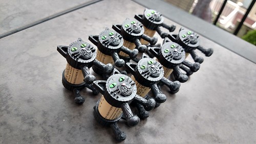
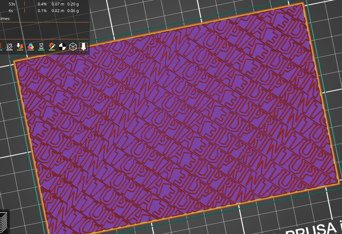
Here’s how I approached it. I’ve only done this in PrusaSlicer, but I believe the steps should be similar in other Slic3r-based slicers like Bambu Studio and Orca. I’ve done three infills now – the original ERRF, one for 3DPrintopia, and my favorite some tessellated hearts!
Note: Not everything in this giant post is going to apply to you, but the information is there for those who will find it handy. If you need a TL;DR, the most basic steps would be:
- Get the source code on your development machine.
- Plan out the “output points” for your pattern. This could be low-tech like graph paper or you could use a tool like Blender.
- Update the code. The impacted files would be:
- libslic3r\Fill\FillPlanePath.cpp – Add your logic to define all your output points.
- libslic3r\Fill\FillPlanePath.hpp – Add declarations for your new infill functions in FillPlanePath.cpp.
- libslic3r\Fill\Fill.cpp – Add in a new case into the surface_fill.params.pattern switch statement.
- libslic3r\Fill\FillBase.cpp – Add a new case into the new_from_type switch statement.
- libslic3r\PrintConfig.cpp – Add new values into:
- s_keys_map_InfillPattern.
- Fill pattern options in PrintConfigDef.
- libslic3r\PrintConfig.hpp – Add a new value into the InfillPattern enum.
- libslic3d\PrintObject.cpp – Optional – you can add in a new case for determine_bridging_angle.
- Test your infill.
- Print!
Getting and Building the Source Code
I think for me, the longest step was getting the source code ready and initially compiled on my machine.You can get the source code of the slicer you want from GitHub:
PrusaSlicer Souce Code
Bambu Studio Source Code
Slic3r Source Code
Building On Your Development Machine
The PrusaSlicer doc folder on GitHub has “How to Build” instructions for Windows, Linux and MacOS. Like everything Prusa does, the documentation was thorough and helpful! I’m working on a Windows machine, so I used the “Building PrusaSlicer on Windows” instructions. I think the instructions did a great job of highlighting the prerequisites and walking me through the process.
Planning The Infill
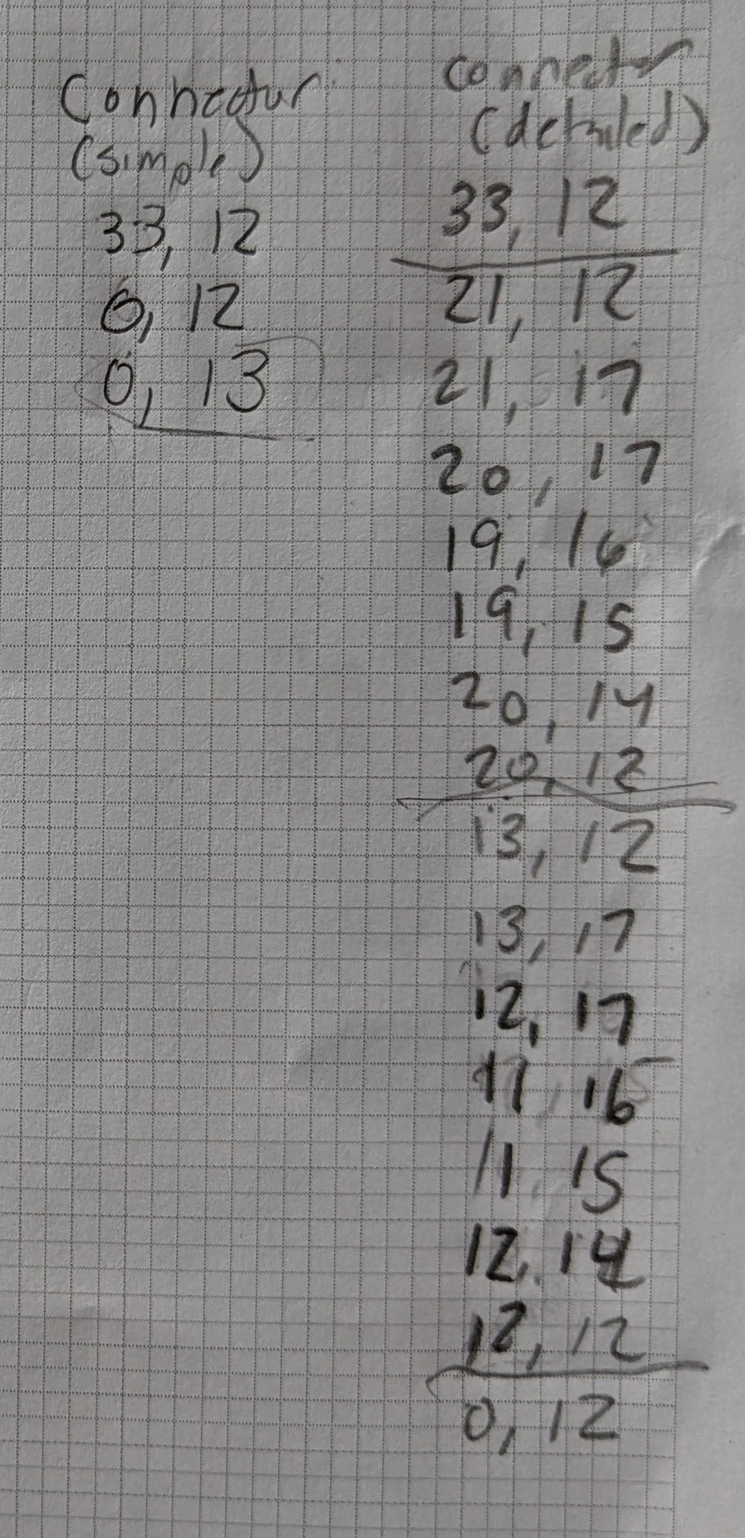
The code is in C++ which I hadn’t worked with in over two decades. Luckily, one can be rusty in C++ and still copy and paste! I started by looking through the infill code in the libslicer\Fill directory. The FillPlanePath.cpp is where I ran across the Hilbert Curve. It was pretty much just making a large collection of points for the infill, like connect the dots. That meant I just needed logic to come up with my points. Once I make all my output points, all the existing code does the rest.
Planning with Graph Paper
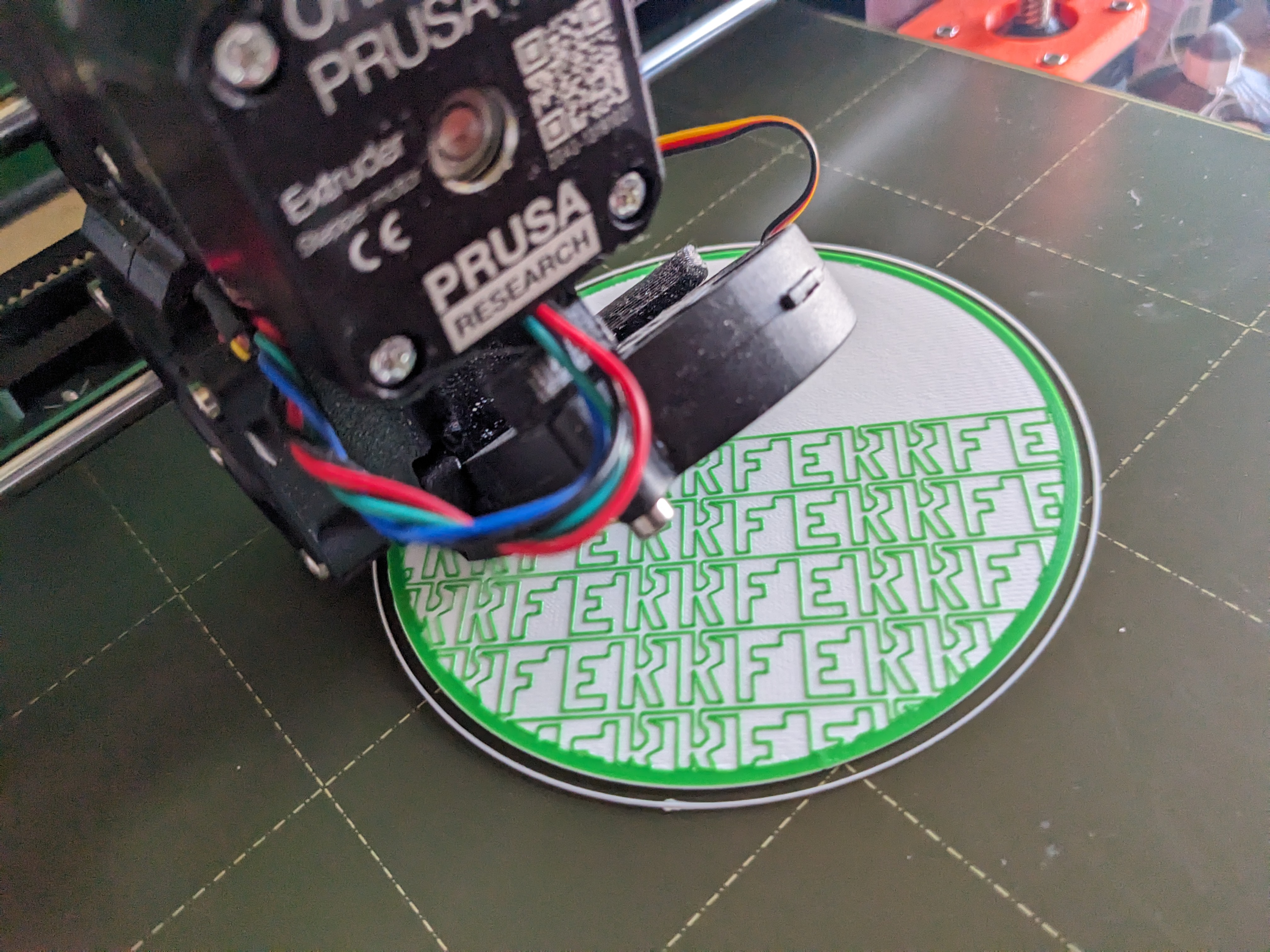
I decided on my points for the ERRF infill and the 3DPrintopia Infill in a decidedly low-tech way. I got out graph paper, I drew what I wanted and planned my points.
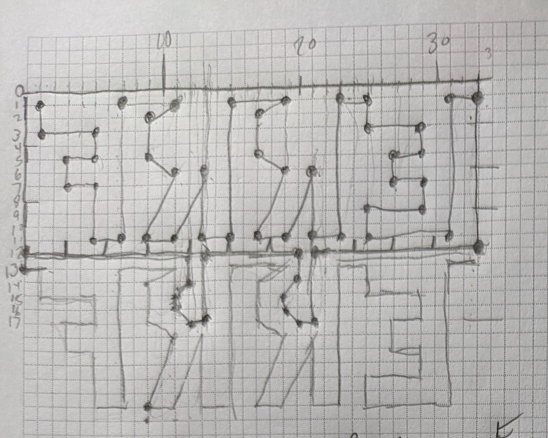
Tip – One best practice I learned is if you are doing text and you want it readable from the top of your print, you’ll want to plot your points backwards (a mirror image of what you want).
When you are planning your infill, think about it as one continuous line. This also means considering how you are going to start a brand new line of your pattern. You don’t want the printer to draw (or collide!) with lines that were already printed.
You could address it like a typewriter where at the end of each line, you add in some points that get you back to the beginning for the next line. With the ERRF and 3DPrintopia text, that journey back to the start gave me an opportunity to refine my letters more. With a continuous path the R’s were pretty basic, but on my way back to start a new line, I could take a quick “detour” and draw some little holes in my R’s.
If you look again at my ERRF graph paper, you’ll see two sections of points. First, I have my points that draw my base letters which can be repeated as much as necessary.
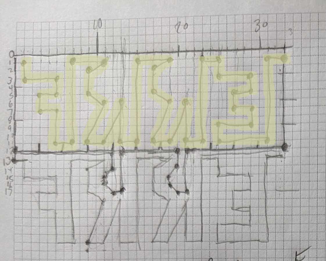
Then for the return back to the start of the beginning of the “page”, I have my points to fill in extra details for the letters to come.
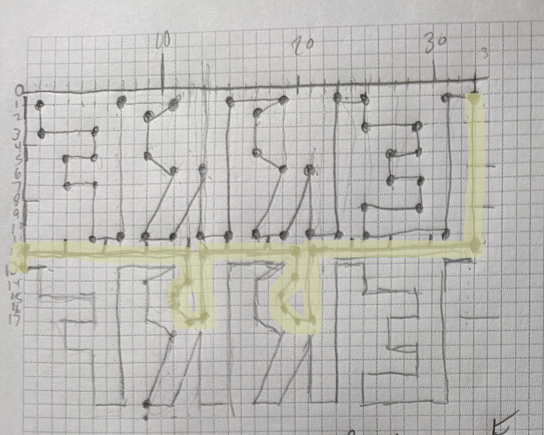
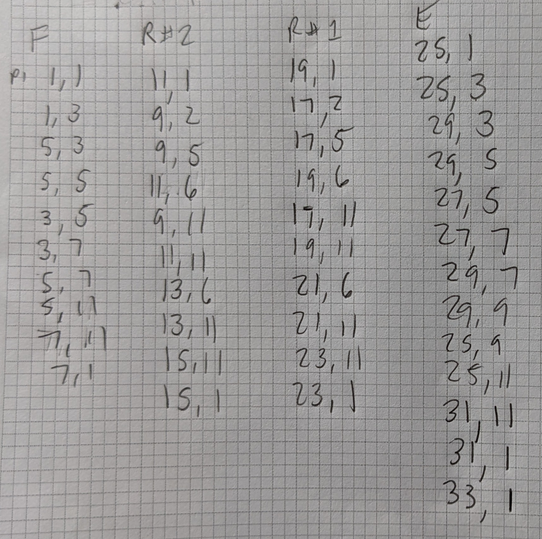
I translated both of those to x/y coordinates using the graph paper as a guide.
Planning The Infill (With Blender and Python)
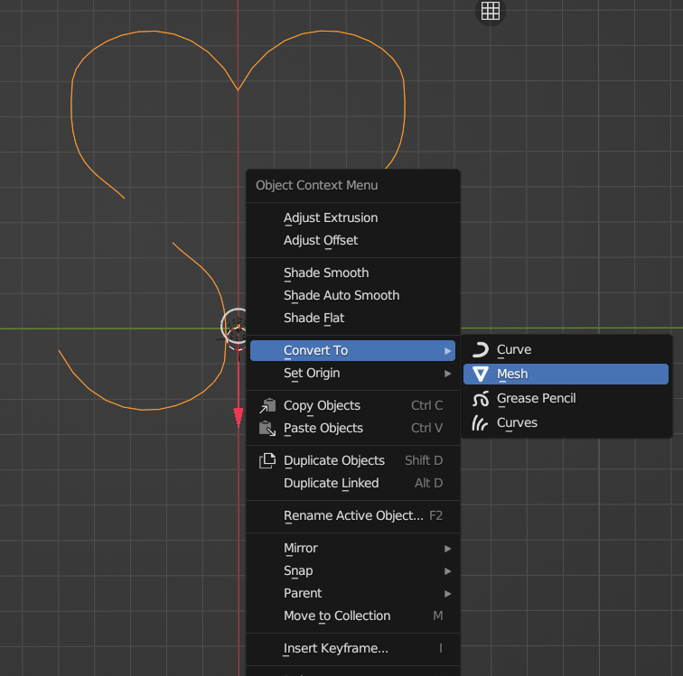
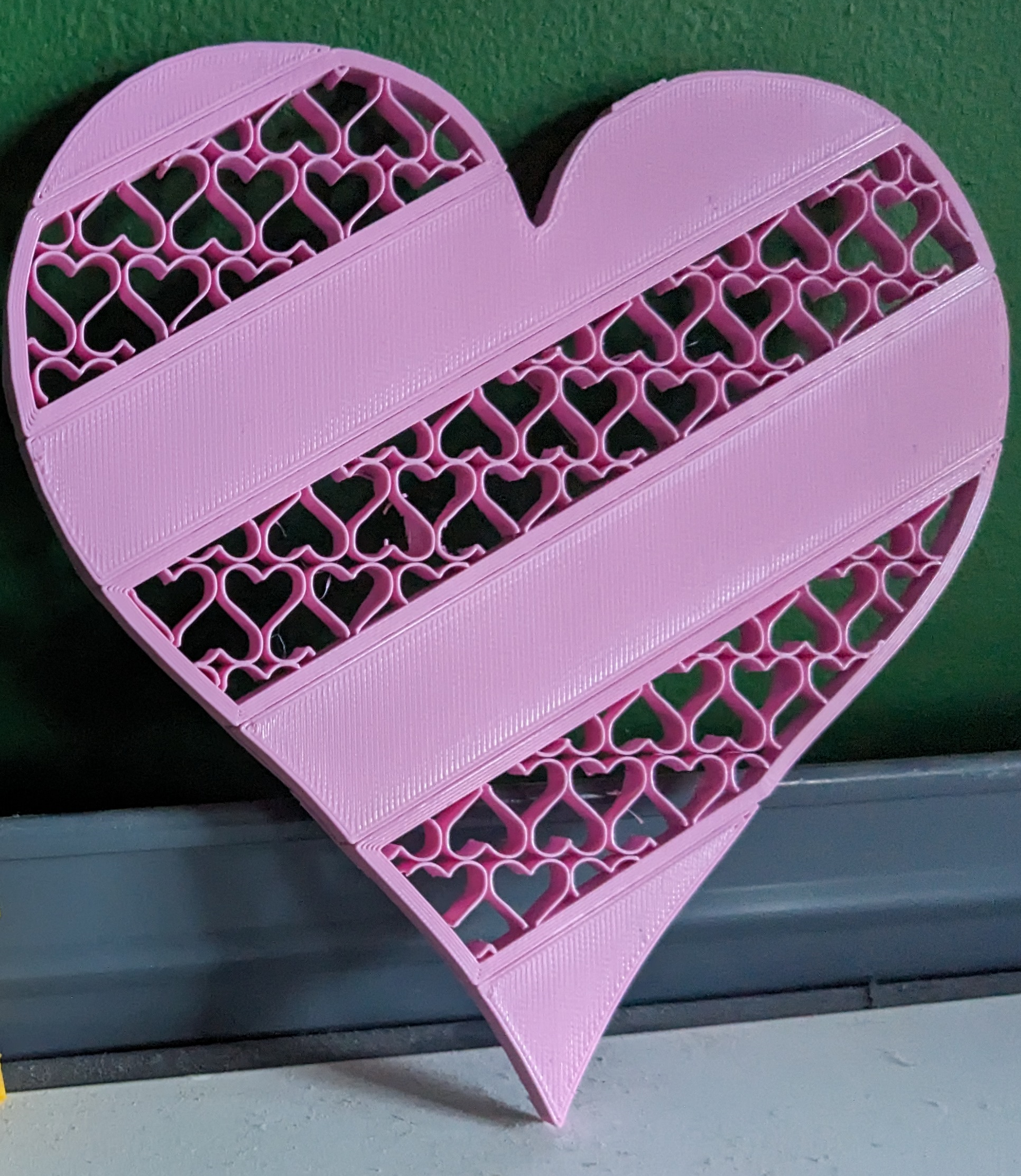
The heart infill, I expected to be more complicated and with more points, so I attacked that in a different way. In Blender, I used a Bezier Curve to draw my heart (with an Array modifier to give me an idea of how it would look with repetition). Once I was satisfied with the shape, I right clicked on it and chose Convert To -> Mesh.
That converted my curve to vertices/points. Instead of graph paper, I could then refer to Blender’s coordinate system to get my output points.
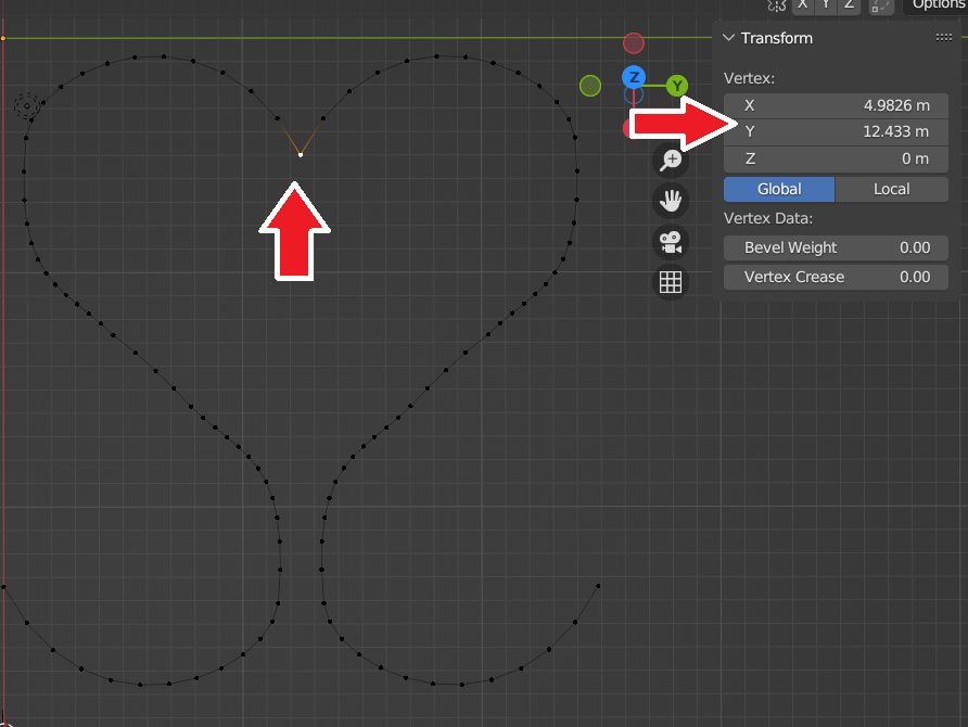
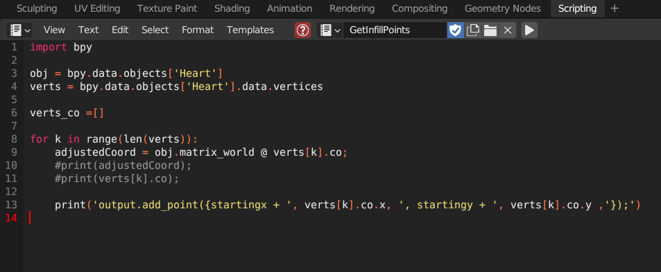
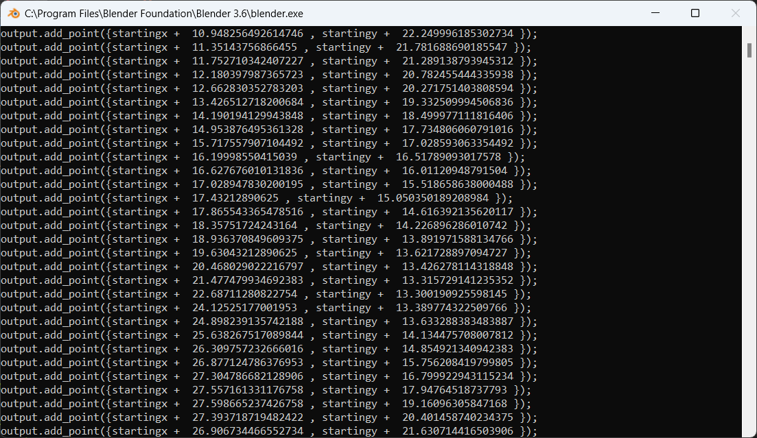
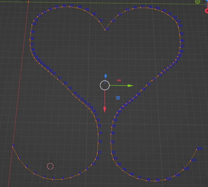
The heart was a lot of points and it was going to be a wee tedious to grab the X and Y coordinate of all 106 vertices. In this case, I decided to speed up the process using a Python script. Under the Scripting tab, I ran the following code to not only get my coordinates, but write out the lines of C++ code I would ultimately need for the slicer (more later):
Viewing Results in the Blender System Console
If you are new to Python scripting for Blender and are wondering how to see the results of all your “print” commands, go to the Window main menu and hit Toggle System Console.
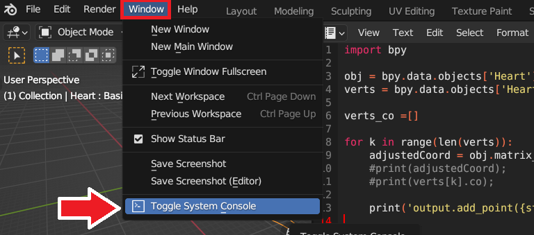
This will give you access to a Command window where you can see the fruit of your labor.
Sorting the Vertices in Blender for the Python Script
I was so excited when my code worked but when I started spot checking I noticed my vertices were not in order. This was going to be an issue because I’m aiming for a continuous line for the slicer to draw. My vision is not going to come to life if the tool path isn’t going in order. I needed to figure out a way to control the order of the output points.
In Blender, vertices are assigned an index as they are created. In Overlays, if you check Text Info, you can see those indexes.
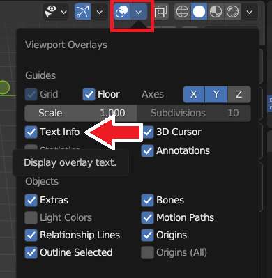
Doing so revealed that my vertices were dreadfully out of the order and that was trickling down to the output points my Python script was so helpfully making for me.
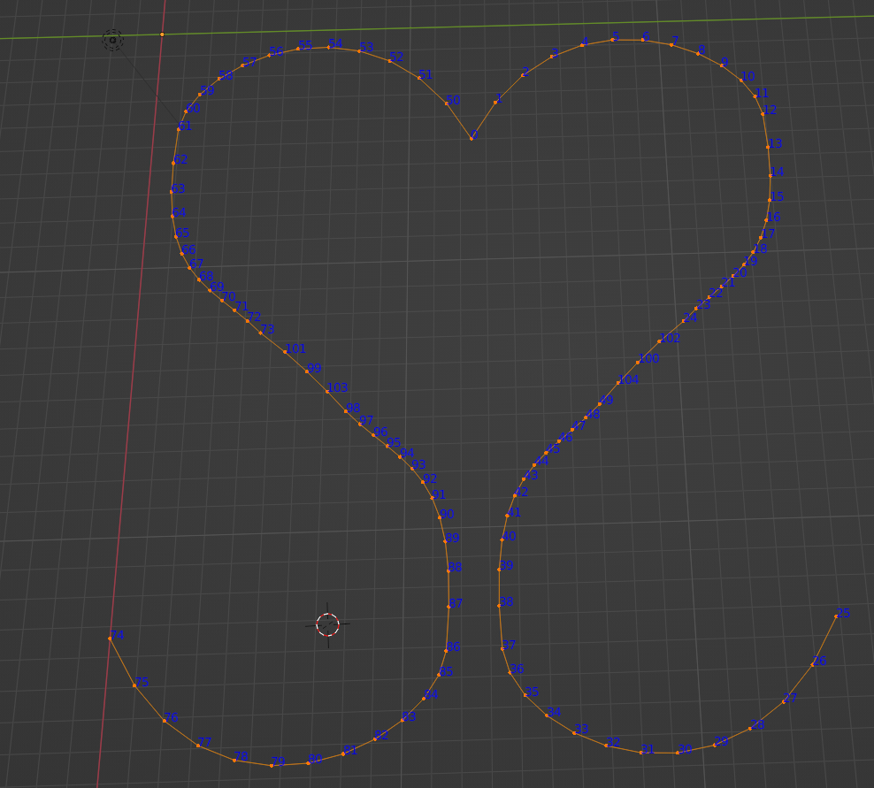
I could have considered changing my Python code, but I ended up using a nice “Shape Keys” Hack by StackOverflow user leander. Once I did that, my points where going from 0 to 101 in the order that I wanted the slicer to draw them.
Using ChatGPT to Reverse the Points
With the ERRF and 3DPrintopia infill when the nozzle was traveling back to the starting X coordinate to start a new line, I was using it to fill out the letters more. I didn’t need that for the hearts, so on the way back, I just wanted to draw another row of hearts…but in reverse. I got that code by pasting in my original code and asking ChatGPT to reverse it for me. It did a good job!
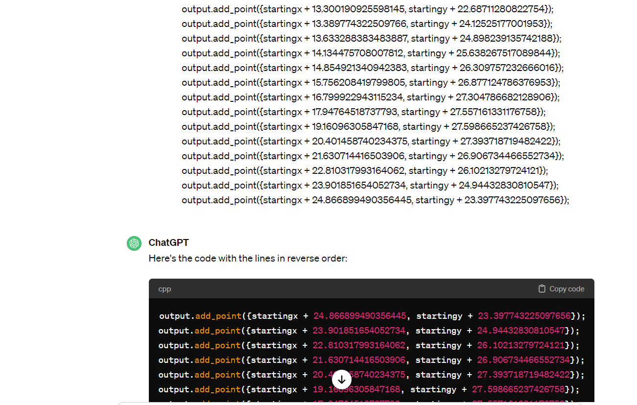
Arguably a better way to approach that would be to create an array of all the points then it would be easy to print them forward or backwards. But hey, this way I finally got to use ChatGPT for some coding. 🙂
Coding the Infill
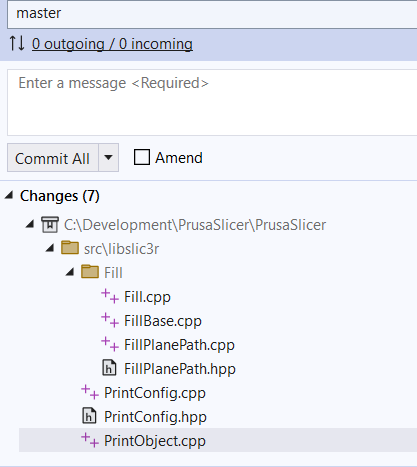
With the actual coding of the infill, there are seven files in the PrusaSlicer-master solution that are updated. If you don’t want to hash through this blog post, another thing you could do is simply search for “hilbert” in the code to locate the spots you need to revise. That’s what I originally did!
I’m including marked up screenshots of the code changes and then I’m also including GitHub Gist excerpts where you can copy and paste.
Tip – With the GitHub Gist examples, if you click on the filename at the bottom of the code and then click on Revisions, you can see what lines were changed (with existing functions).
‘
libslic3r\Fill\FillPlanePath.cpp
This is the file where all the action is. I pretty much copied two functions, renamed them, and updated them for the infill I was working on:
- void FillHilbertCurve::generate
- static void generate_hilbert_curve
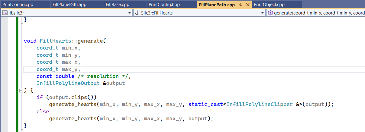
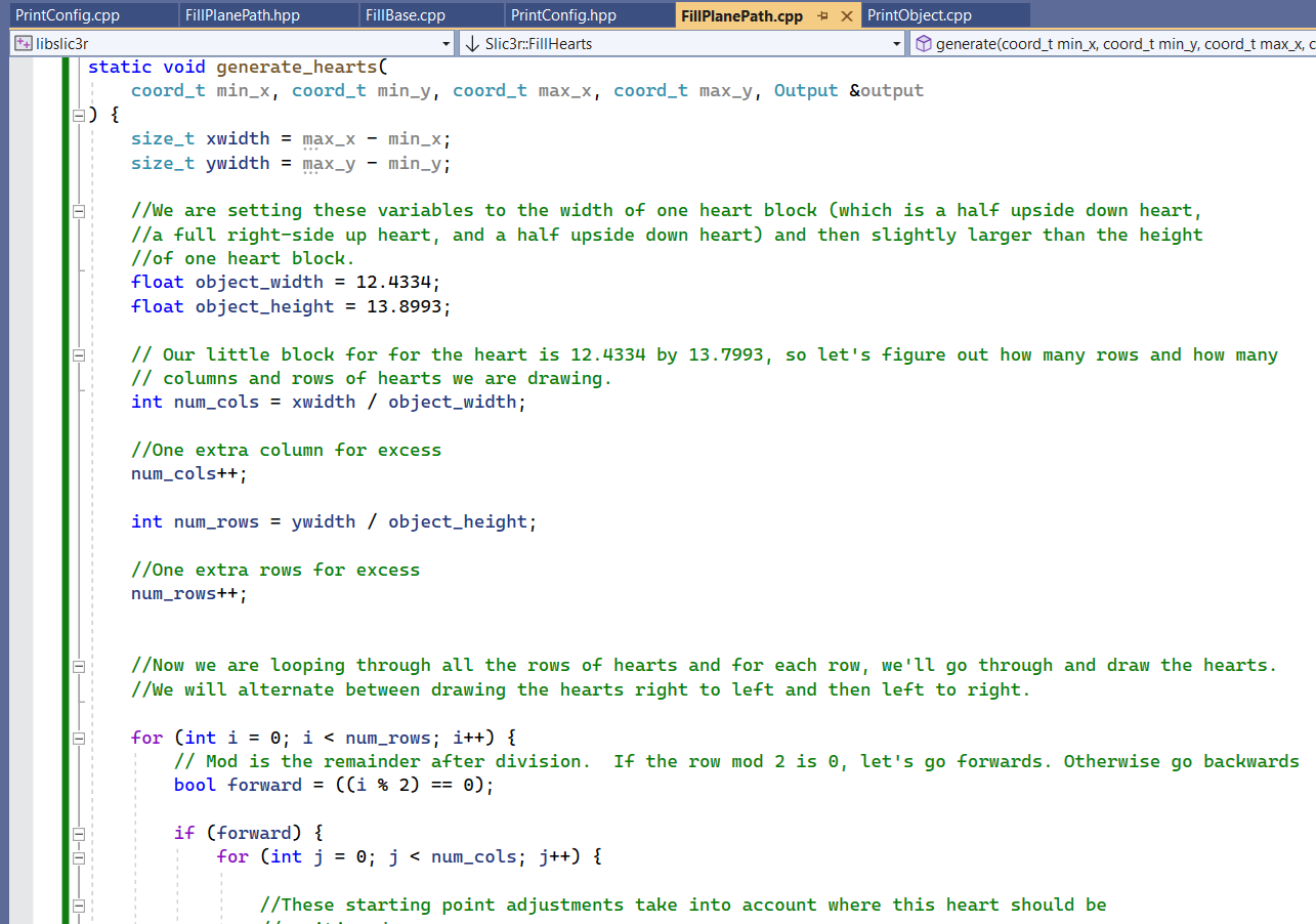
FillHearts::generate
This function is a straight copy of the FillHilbertCurve::generate. The only difference is it is renamed.
generate_hearts
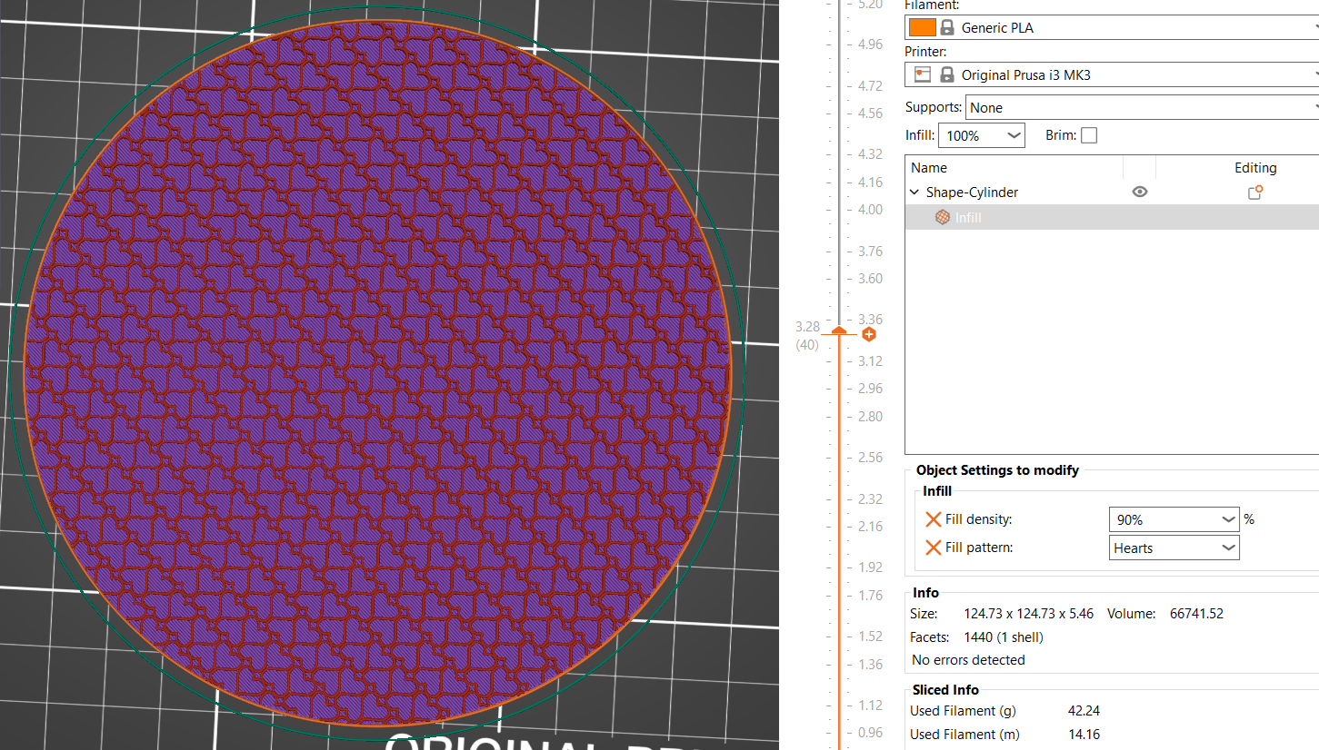
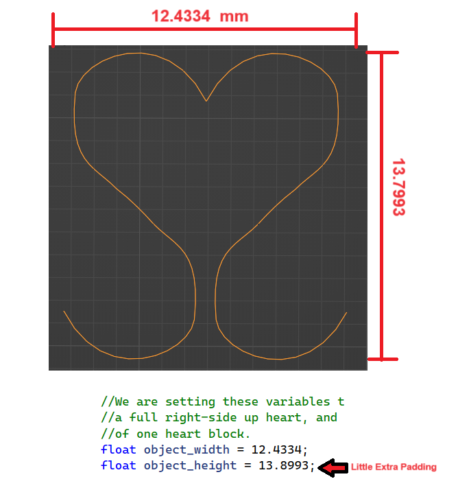
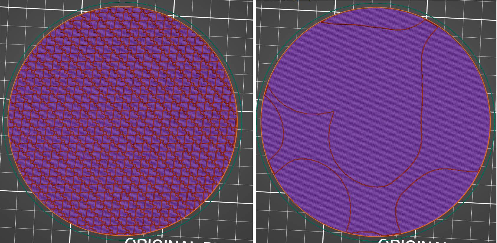
Thanks to the hard work of all the code contributers before me, the generate_hearts function first determines how many columns and rows of hearts we’ll want to print. This is based off the object_width and object_height variables which I set according to the size of the pattern. With the Hearts example, one heart section is 12.4334 mm wide and 13.7993 mm high. My code added just a little padding to the height for aesthetic purposes, but for the most part, you can fill in the dimensions of your pattern block.
The generate_hearts function already receives the minimum and maximum x and y coordinates for the 3D model. It is simple division to determine how many rows and columns of hearts would be needed.
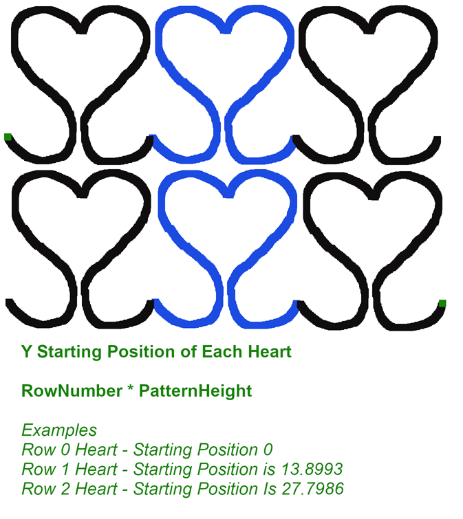
Once we know how many columns and rows of hearts we’ll need, it is two nested loops to go through and add all our “output points”. The first goes through all the “rows” of hearts and the second one goes through all the “columns” of hearts.
When we are determining the y coordinate of a single heart block, we are adjusting the coordinates from Blender based on what row the heart is in.
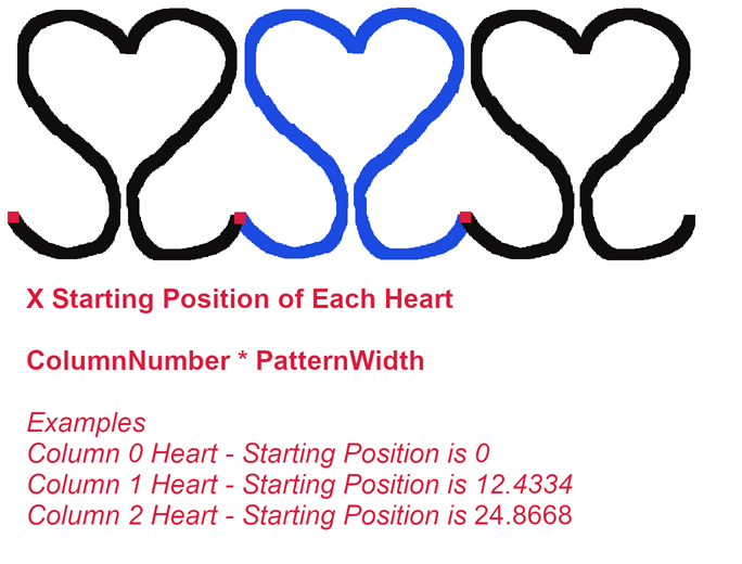
Similarly, the x coordinate is adjusted based on the column the heart is in.
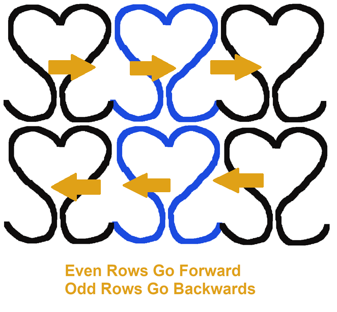
To keep one continuous line, the rows of hearts alternate whether they are going forwards or backwards. The even rows, including the very first one (Row #0) draw forwards. The next row, an odd row, also loops through the columns, but it goes backwards to draw the hearts in the opposite order.
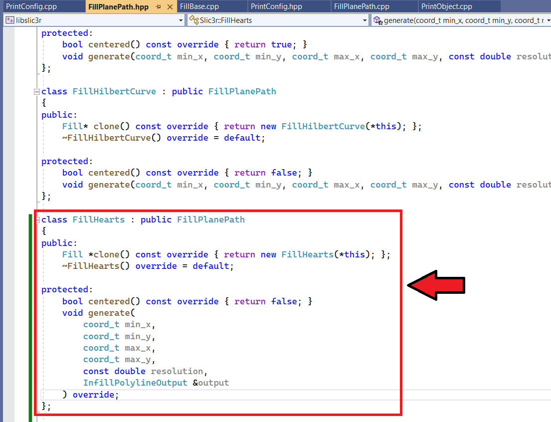
libslic3r\Fill\FillPlanePath.hpp
In this header file, we are going to put in declarations for our new infill pattern. Here I shamelessly copied the FillHilbertCurve code and adjusted it for Hearts.
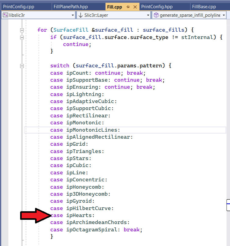
libslic3r\Fill\Fill.cpp
In the switch statement for surface_fill.params.pattern, we add in a case for the new infill pattern (ip).
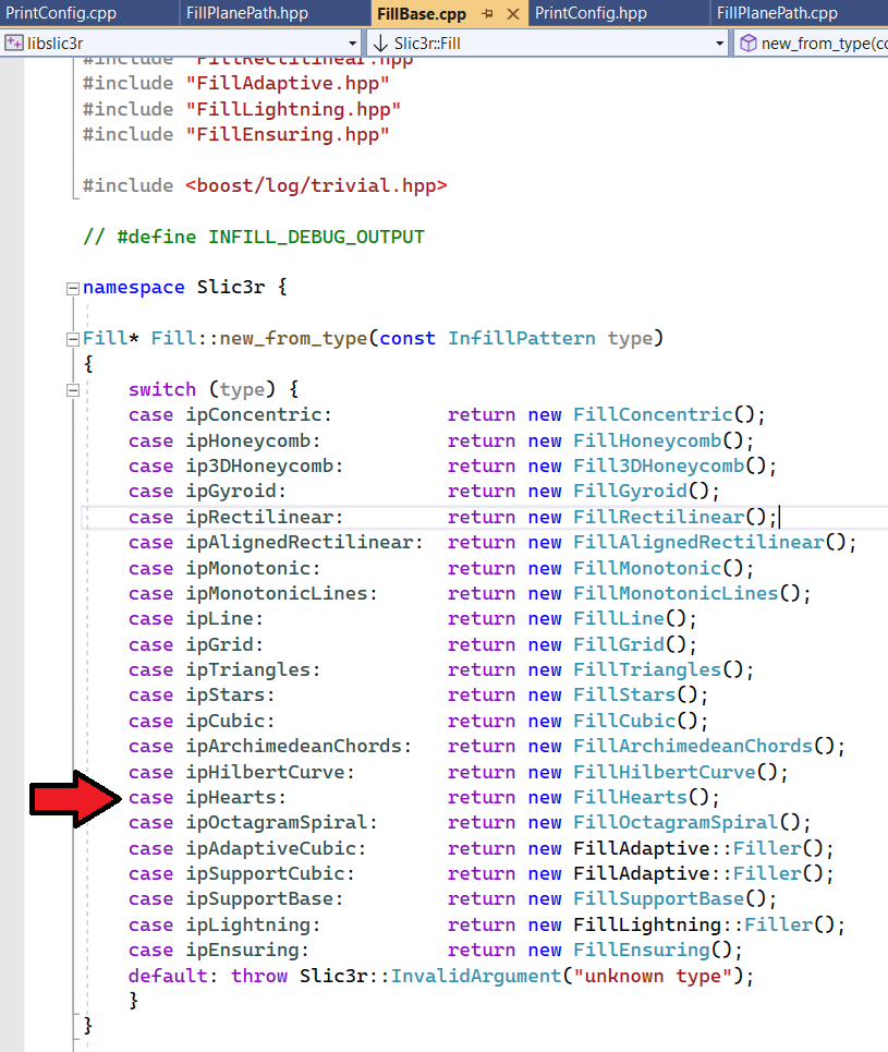
libslic3r\Fill\FillBase.cpp
In the switch statement in the new_from_type put in a case for your new infill pattern (ip) and return a call to your new function for drawing the infill.
libslic3r\PrintConfig.cpp
There are two changes in the PrintConfig.cpp file.
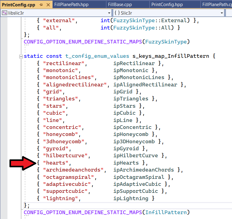
s_keys_map_InfillPattern
In s_keys_map_InfillPattern, we are setting up a new enum with our option.
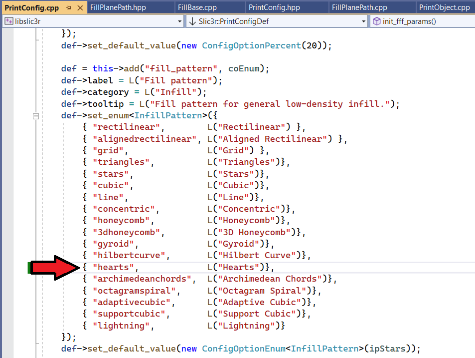
Low-fill infill density
Under PrintConfigDef function, we are adding a new entry to the low-fill infill density pattern.
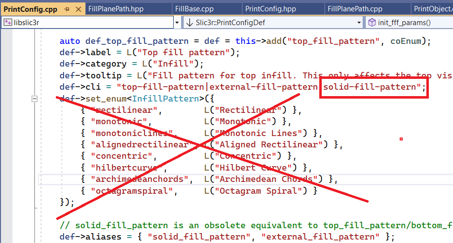
Solid/Top Infill
You do not have to make any changes to the solid/top infill section.
libslic3r\PrintConfig.hpp
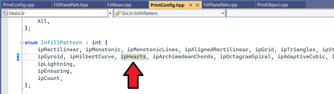
Update the InfillPattern enum to include our new infill pattern (ip).
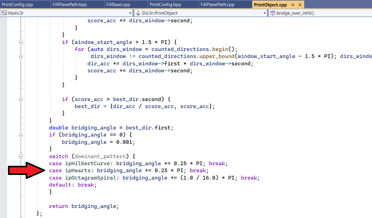
libslic3r\PrintObject.cpp
Optional – in the determine_bridging_angle function, add logic for the new infill pattern. I just copied and pasted from, you’ve guessed it, the Hilbert Curve. 🙂
Testing the Infill
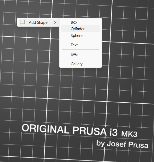
One of the most crucial steps is testing your infill. One easy way to do this is once your code is running and your PrusaSlicer comes up, right click on the bed and choose Add Shape and add a quick Cylinder or Box. Update your infill setting and give it a whirl!
Just like any other code, you may have some debugging opportunities. These could just be benign like a missing point in your logic.
But they could also be things that are detrimental to the health and happiness of your printer.
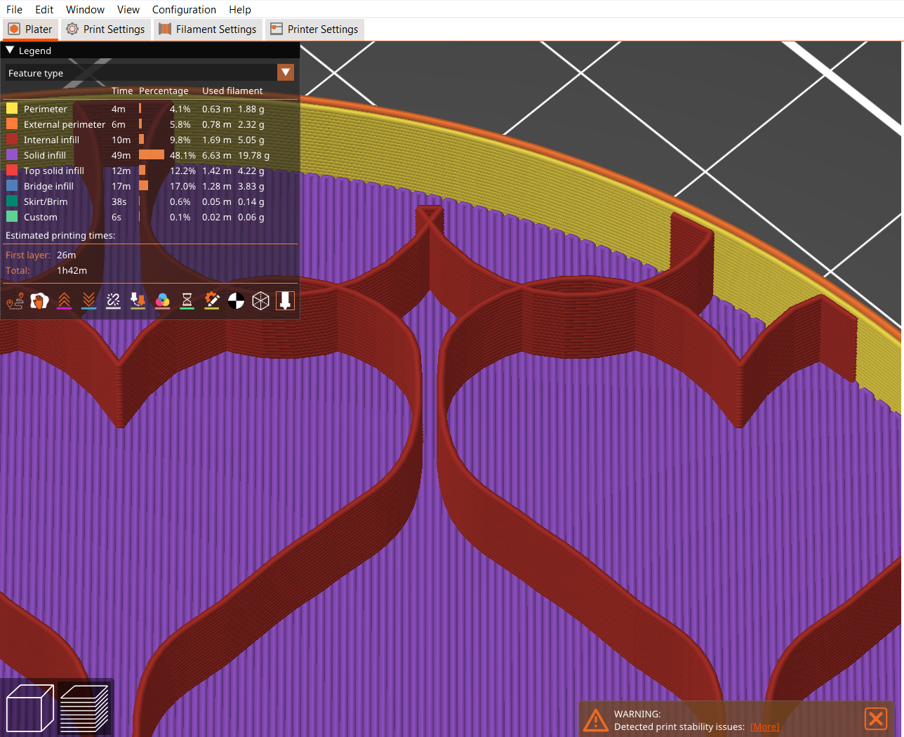
When you slice, if PrusaSlicer gives you a “Detected print stability issues” warning, pay attention.
One neat thing about the code is it already handles the different infill percentages. You don’t have to write any code for that… though I think it is all relative. I don’t think the percentages are going to be an accurate assessment of how filled your object is. 🙂
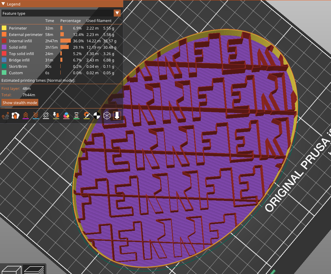
Print Your Infill!
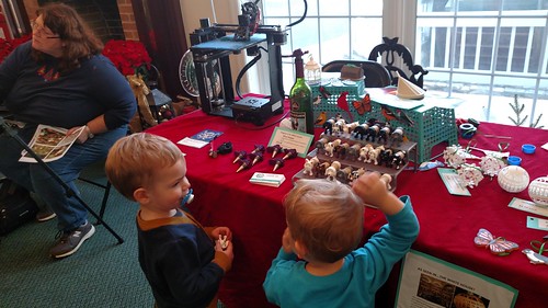
Admittedly, there are not a lot of practical applications as infill is usually hidden away inside the print. That said, there are a lot of aesthetic applications when you start removing top and bottom layers and even more so when you start to use modifiers to only expose infill on certain parts of your object!
Desktop Makes has some great examples of exposed infill ornaments and this video from Prusa3D is a great illustration of what can be done with modifiers.
Good luck and enjoy!