Category Archives: Slicing

Simplify3D’s Print of the Week!!!

Well now, that was a surprise.  I started getting some unexpected Twitter and Facebook notifications.  I was surprised to find I was highlighted by Simplify3D for their Print of the Week.


This five color print is for a friend in Crookston, Minnesota.  I, of course, use my beloved Simplify3D Multiple Processes.  I believe it is my largest multi-colored print– it took up the whole bed of the MakerGear M2.

I’m glad Simplify3D enjoyed the print.  I hope my friend does as well!!! 🙂

Filling 3D Prints with Sand

One of my Maker Faire Nova experiments was filing prints with sand. I am still new to the process, but already had a few tips to pass along.

And since it has been a while since I went into detail about multiple processes in SImplify3D, I decided to do a tour of my slicing settings of the two prints.

Ending Script of my First Print of the Ribbon:
G91 ; relative mode
G1 Z10 ; lift 10mm
G1 X30; move over 30mm

Starting Script of my Second Print to Finish the Ribbon:
G90 ; absolute mode

Maker’s Muse has a most excellent tutorial on running Multiple Processes together– that is at: https://www.youtube.com/watch?v=OcddlK36OVs

And if you want to try RJ Make’s approach, please see his Embedded Magnetron Video at https://www.youtube.com/watch?v=Ubvs2vgv014

There is a Creative Commons image in this video. It is by Amanda B and you can fill the photo on Flickr at https://www.flickr.com/photos/muddybones/5550623402/

Embedded Magnetron Tubes by RJ Make

Not a project or video of mine, but I just love this example of an embedded object by RJ Make. He shows us how to extra Magnetron Tubes and then uses Simplify 3D to embed it in a print.

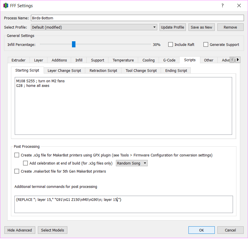
RJ uses a different Simplify 3D technique than I do. I tend to rely on Multiple Processes with custom Starting and Ending Scripts. RJ takes advantage of another section of that Scripts tab. In the Additional terminal commands for post processing, you can set up special code that runs against the G-Code Simplify3D makes to print your object.

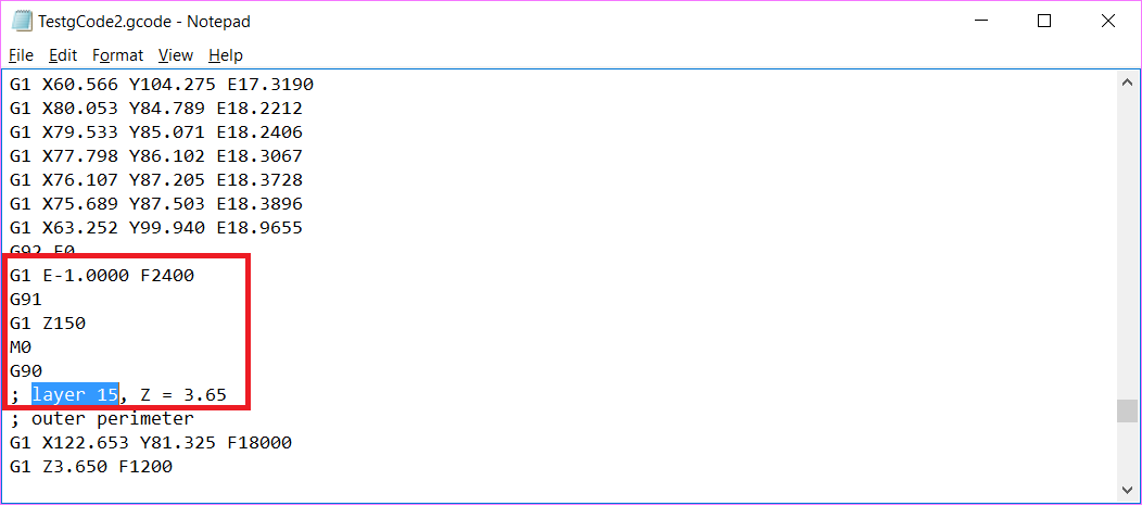
If you pull up your G-Codeinto a text editor like Notepad, you can see that each layer is prefixed with a comment in the G-Code.  In the screenshot below, the text “; layer 15,” indicates the very start of my Layer #15.

Layer15

This gives you a nice place mark and opportunity to do a search and  replace . You use \n for your Carriage Returns. Other than that, everything is normal G-Code.

In RJ’s case, he told Simplify 3D to find the spot in his gCode where Layer 54 is about to begin and he replaced it with:

G91 (putting the machine in relative mode)
G1 Z150 (telling the machine to move the nozzle up 150mm
M0 (the pause command for RJ’s printer)
G90 (putting the nozzle back into absolute mode so it has its bearings when RJ resumes the print).

{REPLACE "; layer 54," "G91\nG1 Z150\nM0\nG90\n; layer 54,"}

I tried it out in my Simplify 3D (for a much smaller print at Layer 15)

Additional Terminal Commands

Simplify 3D compiled the G-Code and ran the Search and Replace, so the additional commands were at the very right spot, right before my Layer 15.

Layer15AfterREplace

One thing that intrigues me about this technique is what I call my “sealing” layers, the layers that will be sealing my object in.  Often these are the very first layer of a brand new process, so they are picking up my First Layer Settings (which I do adjust accordingly).  When you use this technique, the sealing layer would be picking up the bridging settings.

I look forward to giving RJ’s technique a try!

Wanna Learn More?
Documentation on this Simplify3D Feature can be found at: Tip of the Day 8 – Scripts Tab, G-Code


What I Have in the Works for #MakerFaireNova

At the time of publishing this video, I have about 8 days left until Maker Faire Nova on March 19, 2017. More information about the event and tickets can be purchased at http://nova.makerfaire.com/

For my third time participating, I am focusing on 3D prints with embedded elements. With the help of my MakerGear M2, the Wanhao Duplicator i3, and my ever trusty Simplify3D, here’s what I got brewing:

Embedded Prints Within Prints

  • Glowing Anglerfish
  • Multi-colored Gyro Cube
  • Giant Spinning PokeStop*

*I may have attached it differently had I seen Joel Telling’s 200mm bridge first over at 3D Printing Nerd https://www.youtube.com/watch?v=nL0nWJ__PNM : )

Embedded Mirrors

  • The mirrored candleholder
  • A mirrored vase*

*The mirrored vase can also be seen on A Pyro Design’s channel at https://www.youtube.com/watch?v=-IL3q7-osqE

Embedded Nuts

  • Taphandles (as seen in my last video)
  • WIP – Rhododendron Drawer Pulls

Embedded Sand!

  • Standing Cancer Ribbons
  • A dramatic 131 gram difference with Rockledge Mansion Christmas Ornaments

Embedded Split Rings

  • Work In Progress – A long chain of “Kinetic Houndstooth”. What I’m doing with that…. Phew, to be determined.

Embedded Corks

  • A Wine Holder…Made of Old Wine Corks! : )

Embedded Magnets

Embedding Nuts for WORKING Tap Handles!

For this video, I get to share a fun project I did for a new brewery called Heroic Aleworks! You can find them at http://www.heroicaleworks.com

The owners of Heroic Aleworks, don’t just consider themselves brewers, but nerds as well! As a great compliment to their very geeky tasting room (they even have a bathroom painted like a tardis), they have 3D Printed Tap Handles.

This is a great illustration of the “rapid product development” 3D Printing is touted for. They approached me on a Tuesday and we had working Tap Handles by Friday!

To make the tap handles functional, we embedded a standard 3/8″ nut into the print itself to screw onto the keg hardware and that’s where the project got fun!

This video talks about how thinking about the printing orientation ahead of time impacted the design, particularly with the consideration of the hole for the nut.

Nut Animation - Step3

It also goes over my multiple processes in Simplify 3D and my custom starting and end scripts (same old, same old– very similar to what was used for embedding mirrors and the multi colored Gyro Cube).

Design Notes:
Final Dimensions for my Hole for 3/8″ Nut – 15mm x 17.8mm x 9mm
Final Dimensions for Octagon Hole for Bolt – 11mm Diameter

Custom Ending Script for my processes:
G91 ; relative mode
G1 Z100 ; lift 100mm

Custom Starting Script for Third Process
G90 ; absolute mode

Custom Starting Script for Final Process (After Color Change)
G92 E0 ; zero extruder
G1 E25 F225 ; purge nozzle
G92 E0 ; zero extruder
G90 ; absolute mode

Thanks for watching!

Wishing You Many Fails in 2017!

When we are pushing the limits, we are going to encounter fails. But through failure comes knowledge and at times, it even brings about extra creativity. On that note, I hope 2017 brings you many fails!

In December, I did a last minute contribution to the A Pyro Design Maker Coin Holiday Tree. In my coin, I wanted to celebrate the failures that comes along with learning 3D Printing. I call it, “From Failure Comes Knowledge“. This video details the inspirations behind the coin, a little taste of the modeling in Blender, and the [embarrassing] two fails I had printing it.

The From Failure Comes Knowledge Coin on Thingiverse:
http://www.thingiverse.com/thing:1936616/

Check the makers who have already made the coin!

Jim at Another 3D Printing Channel https://www.youtube.com/channel/UCgXpTIrI0KK8_wXMcHLA1fw

Matt at How I Do It https://www.youtube.com/channel/UCJTkCgyQbUU2kpiwhrbLK_A

And of course, Travis and Heather at A Pyro Design
https://www.youtube.com/c/Apyrodesign

Other Models Mentioned in the Video:
The famous 3D Benchy
http://www.thingiverse.com/thing:763622

Drooloop Flowers http://www.thingiverse.com/thing:240158
Furry Vase http://www.thingiverse.com/thing:1800503
Furry Christmas Tree http://www.thingiverse.com/thing:1941557

Thank you so much for watching. Have a fantastic 2017!

Using Inkscape and Tinkercad to Customize Halloween Pendants

HAPPY HALLOWEEN!

My very first Thingiverse upload was glowing pumpkin pendants/pins for kids.  This video hits briefly on how I print these via Multi-processes in Simplify3D (Spoiler alert – they are three separate prints).  It will also show you how you can import in the pendant template into TinkerCAD and quickly make your own customizations.  Finally, have a drawing you want to use?  I’ll go over using Inkscape to make a SVG file from a black and white image/photo/scan that you can also pull into TinkerCAD to “carve” your pumpkin.
All the pumpkin models, including the template are up on Thingiverse at:
http://www.thingiverse.com/thing:1074202
Need help with Simplify3D Multiple Processes?  I learned from THIS Joel Telling video:
https://youtu.be/ZHe2_h1nQG4
TinkerCAD is free with nothing to install– http://www.tinkercad.com
Finally, Inkscape is also free and can be downloaded at http://www.inkscape.org.
The Starting and Stopping Points of My Processes
0 – 1.5mm – Black or Green
1.5 – 2mm – GlowFill
2mm – rest – Orange

Resuming a Print (After Turning Off and Moving the Machine)

axieses

As the Nova Mini Maker Faire came to a close, my demonstration print was far from done. I stopped the print, turned off and unplugged the machine, loaded the machine up into the trunk of my car, drove the 26 miles home (with a strategic stop by Burger King for some yummy yummy Chicken Fries), and set the machine back up at home. A week later, I was ready to start printing again and I wanted to start where I left off. I was able to do so with my trusy MakerGear M2 and Simplify3D. Here’s how!

Homing the Axes
Before I could resume printing, I needed to rehome all my axes so my nozzle had all its bearings, particularly the tricky Z axis. In this case, my print was not very high, so under the Machine Control Panel in Simplify3D, I was able to move the bed around to a good spot for me to hit Home Z without my print hitting the nozzle or the X axis support bar.

Restarting a Print - HomeZ

Homing the Z axis can be trickier with taller prints. Since the MakerGear M2 set its Z-Endstop with a bolt on the side of the bed and it has a removable glass bed, I do have a little “hack”. When resuming taller prints, I remove the glass bed, home all the axes and then replace the bed. Sometimes there is a slight variation with the positioning of the print, but so far it has not been very noticeable in my final prints.

Where to Restart
I know, I know. There are downsides to printing via the USB cable. An upside though– in Simplify3D, you have a continuous update of exactly where the nozzle is, most notably how high it is in the Z axis. In the case of my Maker Faire print, I was the one that stopped the print, so I was able to note and record the exact Z position I stopped off at. That meant I knew exactly what height I wanted to restart the print at.

Restarting a Print - Noting Stopping Point

Sometimes I don’t have that kind of information at my disposal. The other week, I had a filament tangle. I returned to my print to find the printer had been printing nothing for who knows how long. In those cases, I use the Jog Controls tab in the Machine Control Panel to do some sleuthing:

I start with my nozzle way above the print and I lower the Z position until I get close. The closer I get, the smaller the increments I move down, until I am using the -0.1 Z button. When I feel I am pretty much there, I pick an inconspicuous spot on the print and move the nozzle on top of it to make sure the nozzle is just barely above my print. I have found that sometimes touch is easier than sight, so I use a handy dandy business card to gauge the distance. Once I’m satisfied, I only have to refer to the positioning information in Simplify3D to get my Z startng point.

Resuming the Print
Next I tell Simplify3D where it needs to start printing. I do that under the Advanced tab and setting the Start Printing At Height setting.

Restarting a Print - Advanced Tab - Start Printing Height

Finally, I need to give attention to my Starting Script in the Scripts tab. There are steps in the normal start up script I do not want to run. For example, I don’t want to home my axes (G28;)– I already did that manually.  And depending on the object and its positioning on the bed, I may opt to alter other steps that may cause the nozzle to collide with my print. In the case of my Maker Faire print, I made some slight adjustments to the script that has the nozzle go off to the side of the bed to ooze some filament before beginning. I still wanted to do that, but I wanted to make sure the nozzle lifted up high enough (G1 Z10;) to safely cross over my object.

Restarting a Print - Advanced Tab - Custom Scripts

My normal Starting Script went from:

M108 S255 ; turn on M2 fans
G28 ; home all axes
G1 Y50 Z0.3 F9600 ; move forward to avoid binder clips
G1 X205 Z10 ; move off platform
G1 Z0.4 ; position nozzle
G92 E0 ; zero extruder
G1 E25 F225 ; purge nozzle
G92 E0 ; zero extruder
G1 X190 Z0.1 E1.0 F1200 ; slow wipe
G1 X180 Z0.25 ; lift

To

M108 S255 ; turn on M2 fans
G1 Z10;
G1 X205; move off platform
G1 Z0.4 ; position nozzle
G92 E0 ; zero extruder
G1 E25 F225 ; purge nozzle
G92 E0 ; zero extruder
G1 X190 Z0.1 E1.0 F1200 ; slow wipe
G1 Z10 ; lift


Of course, your mileage may vary, but hopefully some of this information translates or inspires a technique that works with your printer and slicer. Happy Printing!

Embedding Mirrors Into Prints with Simplify3D

My sister turned 40 this month and get this– I have never, ever, ever printed her anything. I printed something for her husband, but not her. Bad Vicky! That definitely needed to change. Her house is a very visually stimulating house. They have a variety of lighting and effects– think blacklights, giant flatscreens with screensavers dancing to the music, lasers making patterns on the walls, lava lamps. I wanted my design to fit in and interact with the lighting in her house. I wanted something with mirrors.

Designing
At Michael’s I bought little mosaic mirrors– 35 of them for $1.99.

3D Printing Mosiac Mirror Tiles

Then I got out the trusty calipers. There was some variance in the measurements, but the mirrors were pretty much 15 millimeters by 15 millimeters and 1.75 thick. I designed in cavities into my model for the placement of the mirrors. I used 0.5 millimeter clearance– which meant my “hole” came out to 16 x 16 millimeters and 2.25 thick.

All my design work was in Blender. I decided my design was going to built out of a series of 18 x 18 millimeters squares– each ready to hold a mirror. I used some simple math to figure out how many mirrors I would need to be a good stand for a 3″ pillar LED candle and the ultimate radius of my final product.

3D Printing - MATH!

I made one template square and put in the proper placement of where it would be in the final holder. Another simple math equation told me how many degrees I would have to angle each piece.

360 degrees / # of Mirrors

So for example, in a design with 15 mirrors, each piece would be angled 24 degrees from the previous one. If I did 14 mirrors, each piece would be angled 25.714 from each other.

In Blender, when you rotate items, you are rotating around the Point of Origin of that object (where the little yellow dot appears when you select the Object).

Usually this is the Center of Mass of the object, but guess what! You can control it and the origin doesn’t have to be in the object itself. Once I had my template square in its proper position in the final candle holder, I placed my 3D Cursor at 0,0,0.

Blender - Setting 3D Cursor

I went to Object->Transform->Origin to 3D Cursor.

Blender - Origin to 3D Cursor

This meant the origin was right smack in the middle of my candle holder. It also meant, when I rotate, I rotate around that point.

So I proceeded to Duplicate the square, hit R (for Rotate), hit Z (for around the Z axis) and then type in my angle (25.714).

Blender - Rotate 25.714 along Z Axis

I would then Duplicate that square and Rotate it and so on until I had my entire ring. I did Object->Join to merge all my panel pieces into a single object.

Blender - Object Join

I switched to Edit mode and did some cleanup. I Merged Vertices that were close together and then added in new Faces to fill in the gap.

Blender - Vertices Cleanup

Blender - Filler Faces

The inside of the candle holder is a 14-sided Cylinder. When you add a new Cylinder, you can specify the Number of Sides. I made it match the number of mirrors.

Blender - Inside Cylinder - 14 Sides

I cheated with the placement of the three feet. I added a 3-sided Circle and used that to help me determine where the place my feet.

Blender - 3D Sided Circle To Help with Foot Placement

Under Modifiers I did a Boolean Union on my panel piece, my inside cylinder and my feet and voila– I had a model!

Slicing – Simplify3D
In Simplify3D, I set up two separate processes. The first process ran from the 0.00mm – 17.00mm (You can set that up in the Advanced tab under Layer Modifications). That is the point right before my mirror cavities would get sealed up.

3D Printing with Mirrors - Simplify 3D - Layer Modification Settings for the Bottom

Usually when a process finishes, it’ll run a default ending process– turning off the extruder and disabling the motors, completely dropping the bed. I didn’t want that to happen. In this case, I just wanted the bed to drop down enough for me to put those mirrors in without burning myself and more importantly, get that hot nozzle off my print so it isn’t melting and deforming it and making it hard for me to slide my mirrors in. I went under Scripts and customized my Ending Script. Instead of the usual process, I did two simple steps:

1) I changed it to Relative mode, so my next instruction would use the nozzle’s current position as it’s starting point
2) I told it to move the nozzle up 100mm.

G91 ; relative mode
G1 Z100 ; lift 100mm

3D Printing with Mirrors - Simplify 3D - Ending Script for Bottom

When I prepared just that process for printing, you could see how it was going to stop while I still had openings for my mirrors.

3D Printing with Mirrors - Simplify 3D - Selecting the First Process

3D Printing with Mirrors - Simplify 3D - Preview of First Process

My second process was set up to run from 17.10mm on (again under the Advanced tab)
3D Printing with Mirrors - Simplify 3D - Layer Modification Settings for the Second Process

When a process begins, there are a number of things the printer typically does at the beginning such as turning on the extruder, turning on the fans, homing the axis’s, running off the side of the bed and oozing some filament. I didn’t want to do this for my second process. My axis’s are already homed, my extruder is already heated up, my filament is already flowing. All I had to do was set my printer back to Absolute mode and go. So for this second process, I went under Scripts and customized the Starting Script.

G90 ; absolute mode

3D Printing with Mirrors - Simplify 3D - Starting Script for Second Process

A preview of the second process, illustrates how the mirrors will get sealed in by the print.

3D Printing with Mirrors - Simplify 3D - Preview of Second Process

The process worked out fantastically (Watch it in Action in the YouTube video above– starting at about 7 minutes in).

All in all I did three different designs for my sister.

3D Printing - Embedding Mirrors in Prints

I loved the final product so much I had to make another for myself.

3D Printing with Embedded Mirrors - Heart and Reflection

They ended up looking fantastic stacked. My sister used them as a platform for her Venom action figure. : )

3D Printing - Venon is Victorious on the Mirrored Candle Holders

How To: Avoiding Supports By Using Simplify3D to Cut The Model in Half

After a recent trip the Air and Space Museum’s Udvar-Hazy Center, my husband had a 3D Printing request for me. He wanted a 1934 Buck Rogers Disintegrator Gun.

The Model
Thanks to the great community up on Thingiverse, I didn’t have to do any modeling. I had THREE Buck Rogers Guns to choose from. The one that caught my eye and seemed to most resemble what my husband wanted was “Disintegrator 1934 Buck Rogers Gun” by user bluesroq.

The designer recommended printing the model with supports and there is indeed a lot of overhangs with how the gun is positioning now.

Avoiding Supports
Even though Simplify3D has top notch supports that are easy to remove and easy to control, I wanted to try to avoid supports in this case for a few reasons:

  1. As great as Simplify3D supports are, they would still leave some scarring or souvenirs on the faces– in this case– an entire side of my gun would be subject to that and not look as pretty and finished as the other side.
  2. Supports increase your printing time AND your material usage. In the case of an adult-sized Buck Rogers gun, the print time would have gone from 4 hours 30 minutes to 7 hours 12 minutes!

    Without Supports

    With Supprots

  3. If it were in half, this particular model would be an easy, straight forward print without any troubling overhangs.

Looking over the Buck Rogers Gun, the model itself was very symmetrical. It would be a great model to print in two halves and glue together. As a 3D Modeler, I could easily pull this model into something like Blender and break in half that way. But, I could also save time and just do it through my slicer! : )

Cutting in Half – Simplify3D
In Simplify3D, anything that is below your build plate will get ignored by the printer. So in the case of this gun, I would want to lower it down so half of it is above the build plate and half is below. The steps would be:

  1. First off, it is helpful to see the build plate while you are working. If yours is not displaying in your Simplify3D, click on Prepare to Print and check the Build Table under Show In Preview.
    Simplify3D - Build Plate Not Displayed

    Simplify3D - Show Build Plate

  2. Next we need to figure out how far we want to lower our model. Simplify3D makes that easy for us as well. Double click on your model and in the information panel under the Change Scaling section, we will get a reference of the exact measurements. In this case, we are interested in the height of the model, the Z value.
    Noting the Size
  3. Now we have some simple math. We want to lower the model so only half of it is above the print bed. That means we want to divide the height by 2. In this example– 25.43 divided by 2 is 12.71. In our Change Position section, we want to change the Z offset to -12.71 (aka Lower the model 12.71 mm).
    Positioned Half Under Build Bed
  4. At this point, half of our model is under the print bed! If we click on Prepare to Print, you’ll see that only half of the model is going to be printed.
    Everything Under Build Bed Ignored

Getting the Second Half – Simplify3D
To make a whole gun, we obviously want to print two halves of the gun.

  1. Click on your model to select it and then go to Edit->Duplicate Models and make one more copy. You may have to move it around to a better spot on the build plate. (You can also click on the Center and Arrange— but you’ll have to reset your Z Offset again for the original model).
    Duplicate Models
  2. Now we have to flip our new part. Gotcha– Watch Out for Mirroring! My first inclination was to go Mesh->Mirror Mesh and mirror my second half over the X or the Y axis. That could work for some models, but in the case where there is text on your model (like this), then that also mirrors your text and it too would be backwards. Mirroring should also be avoided if your model isn’t exactly symmetrical and has different detailings on each side.
    Mirror Menus

    Text Backward Mirrored
    D’oh – Backwards Text

    In lieu of mirroring, you can rotate it! Double click the object and then in the Change Rotation section, rotate the model 180 over the X or Y axis. Don’t be alarmed if your object suddenly “disappears”. It’s actually underneath your print bed. You just have to adjust the Z Offset now to move the new one 12.71 above the print bed.

    Rotated 180

Slic3r
I have found Simplify3D to be absolutely 100% worth my money, but if it is not for you or your budget, you are not out of luck. You may be able to do the same thing in your slicer. As an example in open-sourced (and free) Slic3r, once you had your object on your plater, you would go to Object->Cut…

Slic3r - Object CUt

And you can pick the cutting height (and you have options to get both sides and rotate one)
Slic3r Cut in Action

And there you go, you can break your model up without modeling software like Blender. This technique’s applications are not limited to merely cutting objects in half. You can use it anytime you want to isolate out a particular section of a model to print. Say you got a 3D Hubs order and you are worried about a tricky section near the top. You don’t have to waste the time and material to run the whole print to find out that section is going to fail. Instead, you can lower your object down and do a quick print on just the troublesome section to see how it performs.